4. Android Application
4.1 Serial Terminal
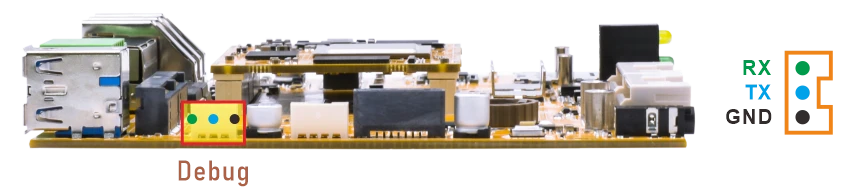
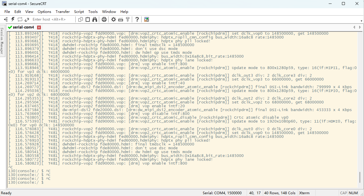
Connect the board and PC with USB Serial cable, then power on, the terminal will output boot information. The default baudrate is 1500000.
4.2 Display
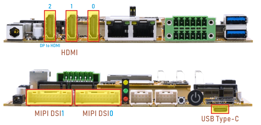
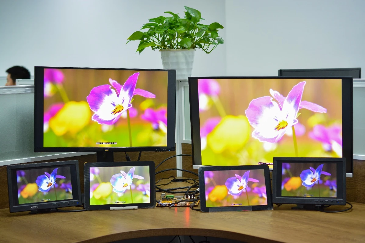
EM3588 supports up to 6-screen synchronized display by default on both Android 14 and Android 16. To achieve synchronized output on similar interfaces (such as HDMI0/HDMI1 or HDMI2/DP Alt Mode), identical display timing must be used. In this case, the maximum supported resolution is 4K@60fps.
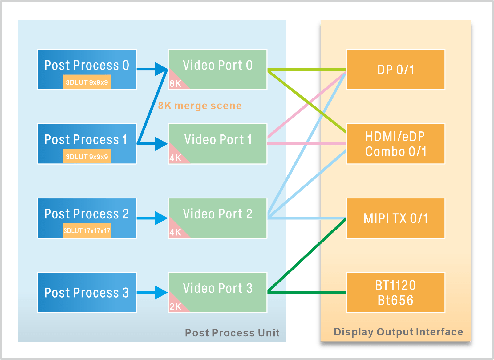
RK3588 Display Output Mapping
4.3 USB
4.3.1 USB-C
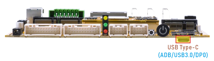
Features supported by the USB-C interface:
Reversible Design: Allows insertion in either orientation for user convenience.
Data Transmission Roles: Supports flexible designation of host and device roles.
Multiple Protocol Support: Compatible with USB 3.0 and DisplayPort, enabling high-speed data transmission.
4.3.1.1 ADB
❶ Connect the board and PC host with USB-C cable.
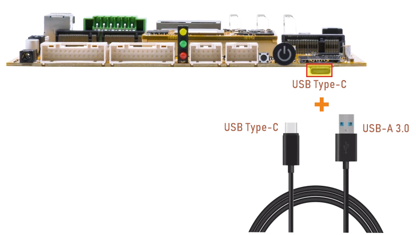
❷ Install ADB driver on Windows system.
❸ Press Windows + R to open the Run program. Type cmd and press Enter
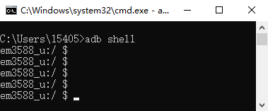
❹ Execute the follow commands to enable ADB.
1adb shell
4.3.1.2 USB Host
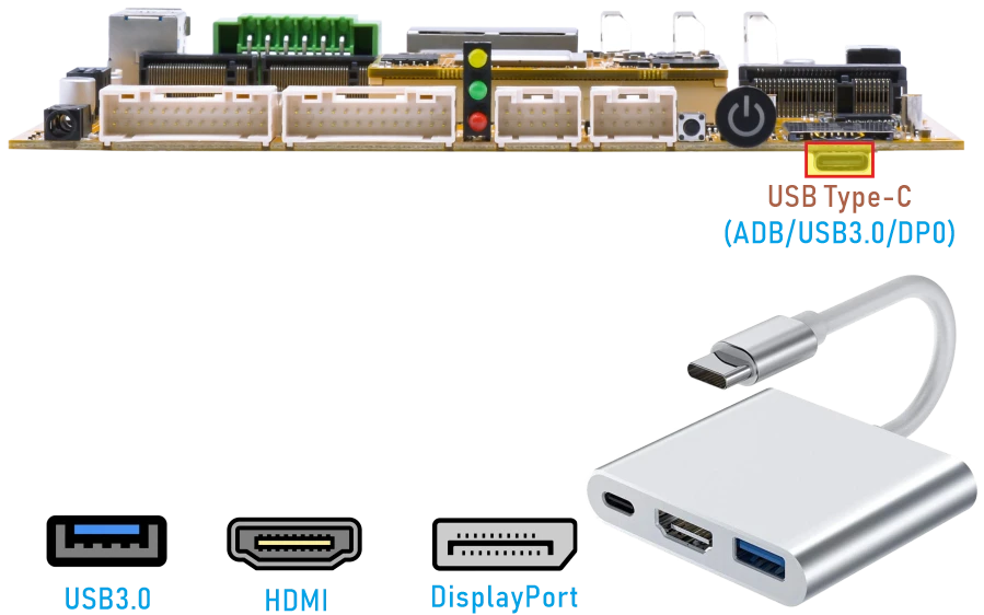
The EM3588 USB-C port supports USB 3.0 host mode through a USB-C to USB-A adapter. After inserting the USB drive, click the Explorer icon to view the mounted drive.
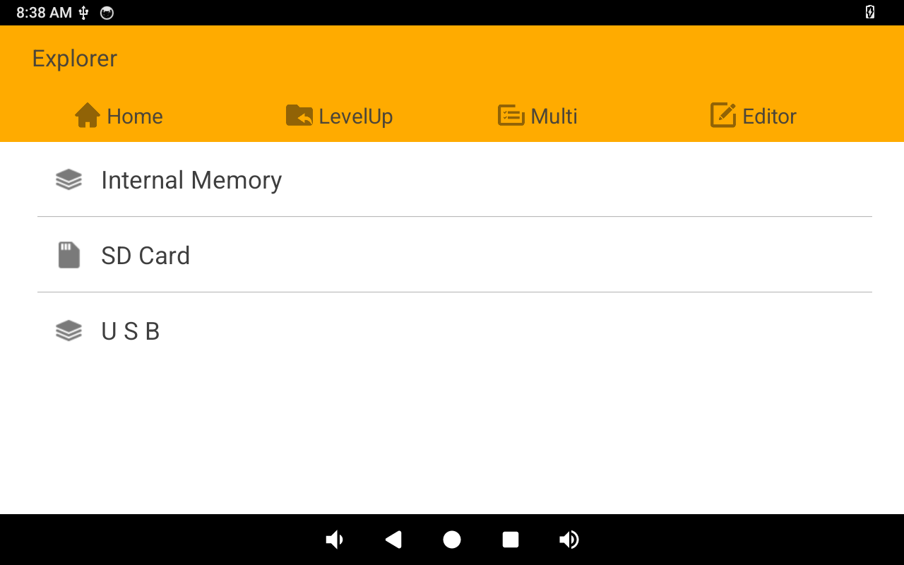
Mounted U-disk
4.3.1.3 DP Alt Mode
DisplayPort Alternate Mode (DP Alt Mode) is a technology that facilitates the transmission of DisplayPort video signals through a USB-C interface. It enables devices to output video and audio via a USB-C connection without requiring a dedicated DisplayPort connector. This allows users to connect a display using a single USB-C port while transmitting video, audio, and additional data.
Boardcon has conducted the testing at USB-C to HDMI/DP (3840 x 2160 @ 60fps).
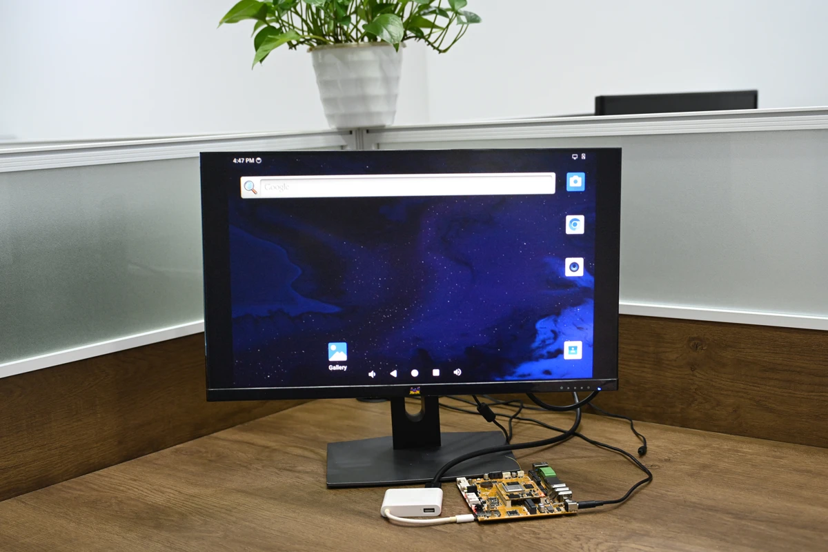
USB-C to HDMI
4.3.2 USB-A (USB3.0 Host)
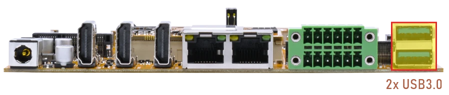
The USB3.0 Host can connect peripherals such as mouse, keyboards, and flash drives. After inserting the USB drive, click the Explorer icon to view the mounted drive.
4.4 Ethernet
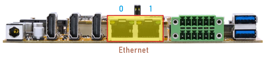
❶ Connect both Ethernet ports on the development board to the router using Ethernet cables.
According to the log, both Ethernet ports are successfully connected.
console:/ $
[  546.277137][ T2864] rk_gmac-dwmac fe1c0000.ethernet eth0: Link is Up - 1Gbps/Full - flow control rx/tx
[  546.277333][   T87] IPv6: ADDRCONF(NETDEV_CHANGE): eth0: link becomes ready
[  557.540887][  T139] rk_gmac-dwmac fe1b0000.ethernet eth1: Link is Up - 1Gbps/Full - flow control rx/tx
[  557.540969][   T87] IPv6: ADDRCONF(NETDEV_CHANGE): eth1: link becomes ready
❷ Test network connectivity.
1ping -I eth0 192.168.0.1
2ping -I eth1 www.armdesigner.com
console:/ $ ping -I eth0 192.168.0.1
ping: Warning: source address might be selected on device other than eth0.
PING 192.168.0.1 (192.168.0.1) from 192.168.0.55 eth0: 56(84) bytes of data.
64 bytes from 192.168.0.1: icmp_seq=1 ttl=255 time=3.03 ms
64 bytes from 192.168.0.1: icmp_seq=2 ttl=255 time=0.420 ms
64 bytes from 192.168.0.1: icmp_seq=3 ttl=255 time=0.300 ms
64 bytes from 192.168.0.1: icmp_seq=4 ttl=255 time=0.343 ms
64 bytes from 192.168.0.1: icmp_seq=5 ttl=255 time=0.604 ms
^C
--- 192.168.0.1 ping statistics ---
5 packets transmitted, 5 received, 0% packet loss, time 4046ms
rtt min/avg/max/mdev = 0.300/0.940/3.035/1.052 ms
console:/ $
console:/ $ ping -I eth1 www.armdesigner.com
PING www.armdesigner.com (67.222.54.196) from 192.168.0.55 eth1: 56(84) bytes of data.
64 bytes from www.armdesigner.com (67.222.54.196): icmp_seq=1 ttl=50 time=190 ms
64 bytes from www.armdesigner.com (67.222.54.196): icmp_seq=1 ttl=50 time=190 ms (DUP!)
64 bytes from www.armdesigner.com (67.222.54.196): icmp_seq=2 ttl=50 time=192 ms
64 bytes from www.armdesigner.com (67.222.54.196): icmp_seq=2 ttl=50 time=192 ms (DUP!)
64 bytes from www.armdesigner.com (67.222.54.196): icmp_seq=3 ttl=50 time=191 ms
64 bytes from www.armdesigner.com (67.222.54.196): icmp_seq=3 ttl=50 time=191 ms (DUP!)
64 bytes from www.armdesigner.com (67.222.54.196): icmp_seq=4 ttl=50 time=190 ms
64 bytes from www.armdesigner.com (67.222.54.196): icmp_seq=4 ttl=50 time=190 ms (DUP!)
^C
--- www.armdesigner.com ping statistics ---
4 packets transmitted, 4 received, +4 duplicates, 0% packet loss, time 3003ms
rtt min/avg/max/mdev = 190.428/191.140/192.173/0.676 ms
4.5 SD Card
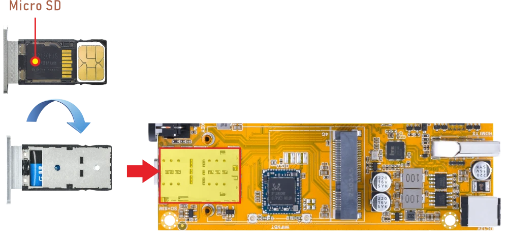
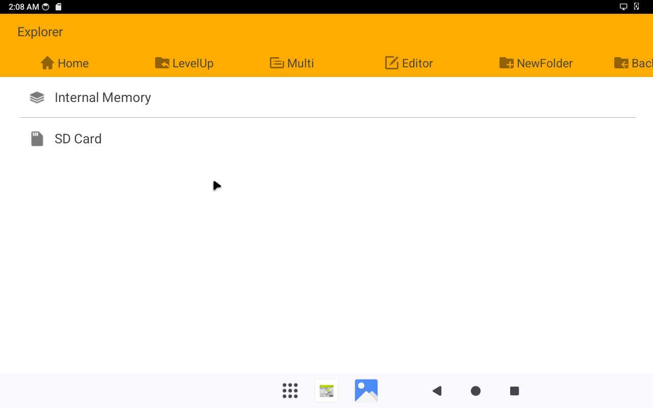
Compact3576 supports SD Hot-plug. Click Explorer to view the mounted SD card.
4.6 SATA
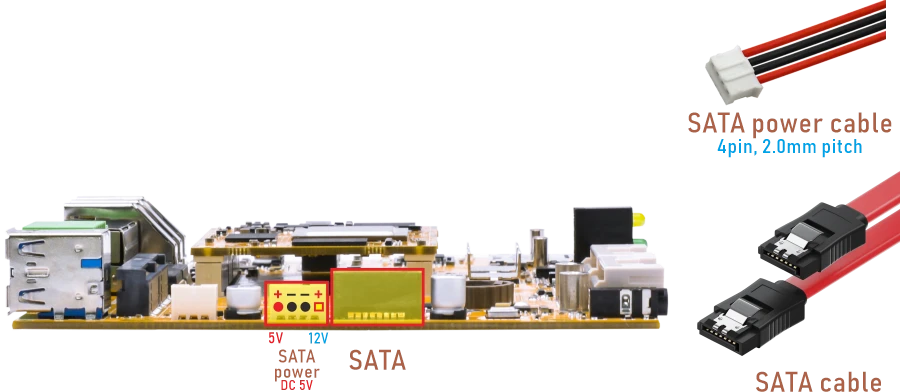
❶ Connect SATA and SATA power(5V).
❷ Power on.
❸ Click Explorer to view the mounted SATA drive.
4.7 M.2 SSD
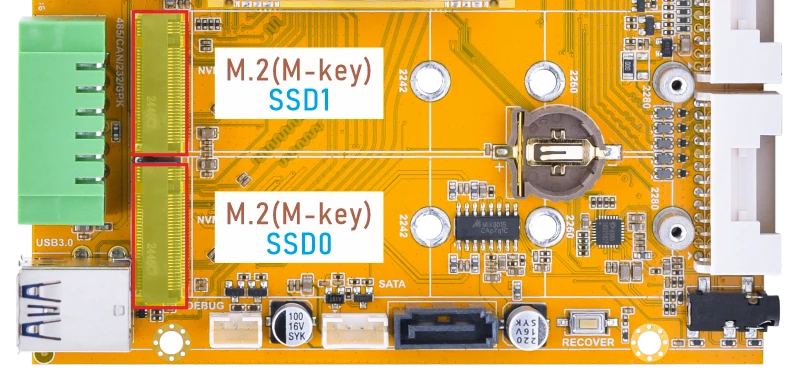
❶ Insert the SSD into the M.2 slot.
❷ Power on.
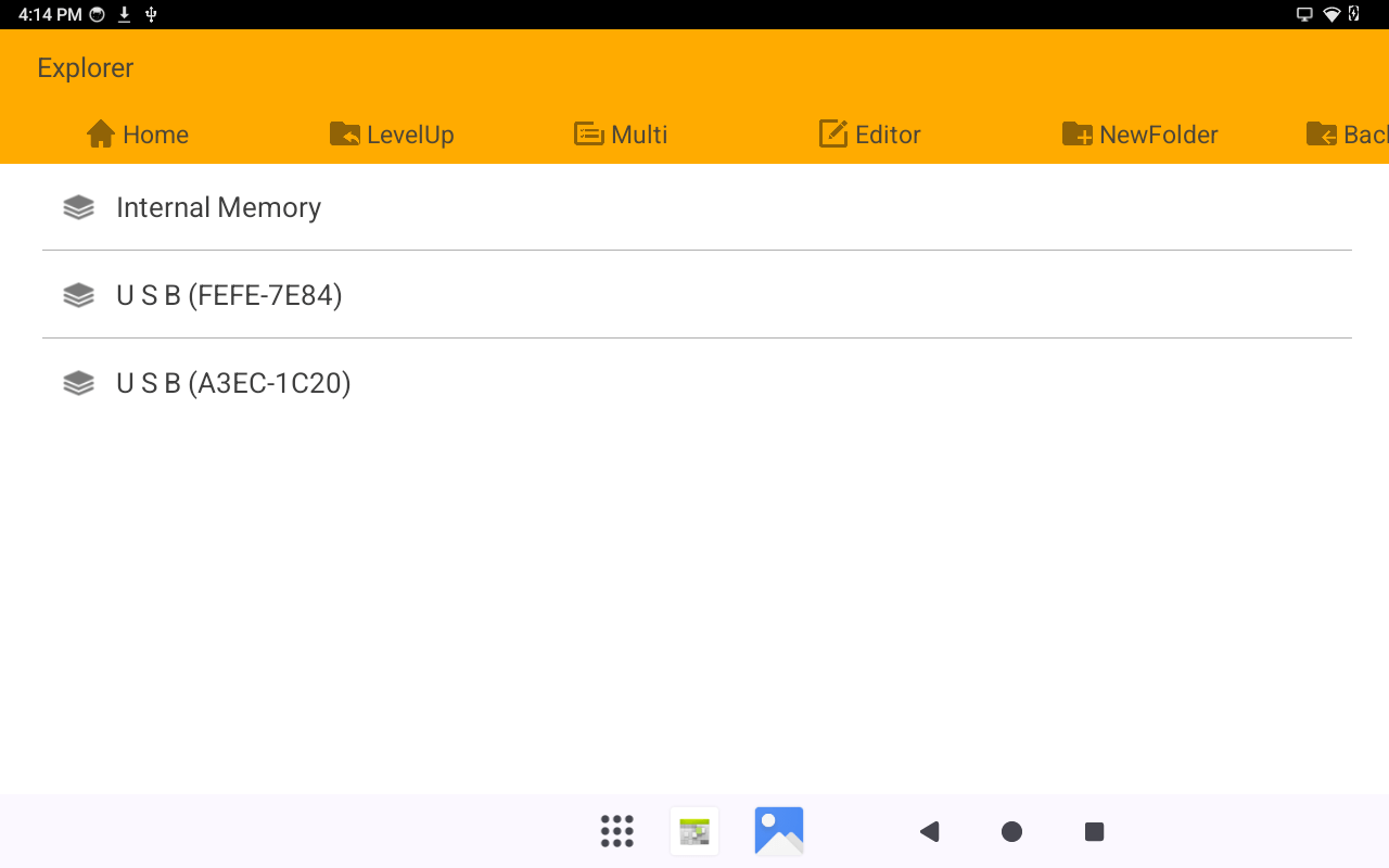
❸ Click Explorer to view the mounted SSD drive.
4.8 WiFi & Bluetooth
4.8.1 WiFi
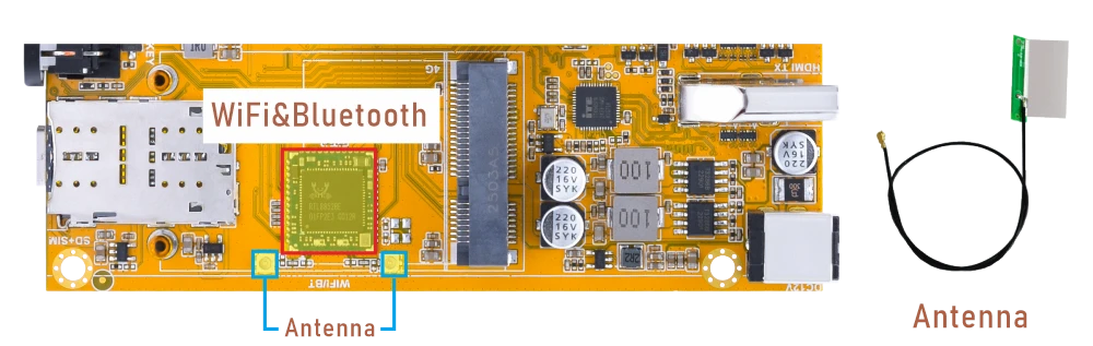
❶ Connect the antennas.
❷ Click Settings -> Network & internet -> Internet -> Wi-Fi -> turn on
❸ Select the SSID from the list of available networks and enter the password.
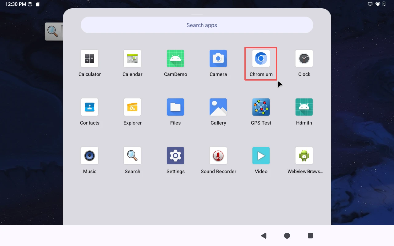
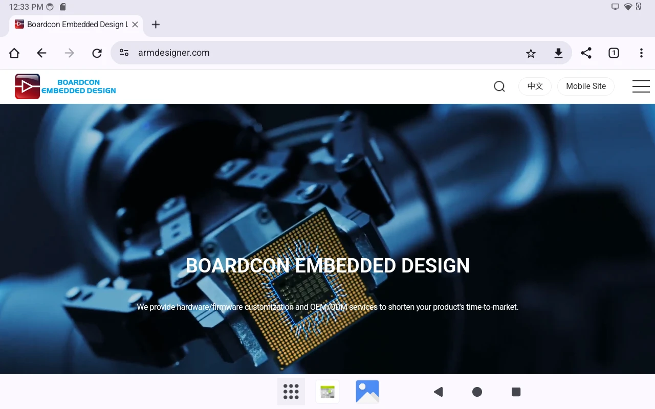
When Wi-Fi is connected, users can verify network connectivity by opening a web page in Chromium, or by running the test commands.
1su
2ifconfig wlan0
3ping -I wlan0 www.armdesigner.com
4.8.2 Bluetooth
Click Settings -> Connected devices -> Pair new device
Select the available device in the list to pair.
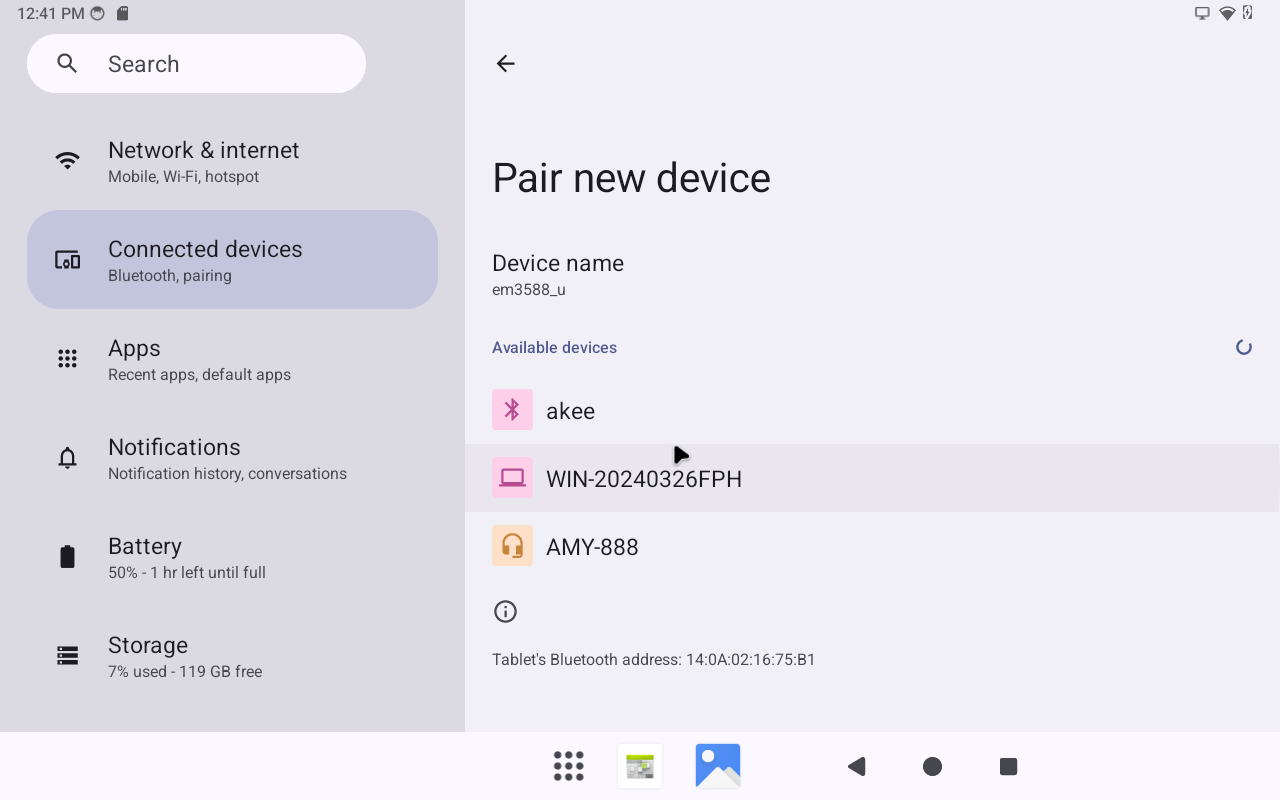
After pairing, devices can connect with each other automatically.
4.9 4G & GPS
4.9.1 4G
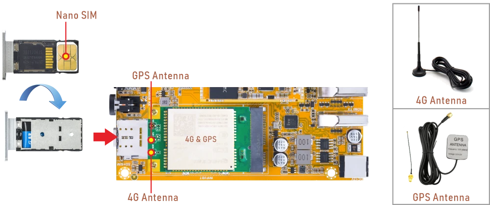
❶ Insert 4G module to mPCIe slot (4G model: EC20).
❷ Connect antenna and insert SIM card.
❸ Power on. The default connection is 4G network.
4G network
❹ Verify network connectivity by using a browser, or by running the test commands.
1su
2ifconfig
3ping -I wwan0 www.armdesigner.com
4.9.2 GPS
❶ Insert the 4G module into the mPCIe slot.
❷ Connect a GPS antenna.
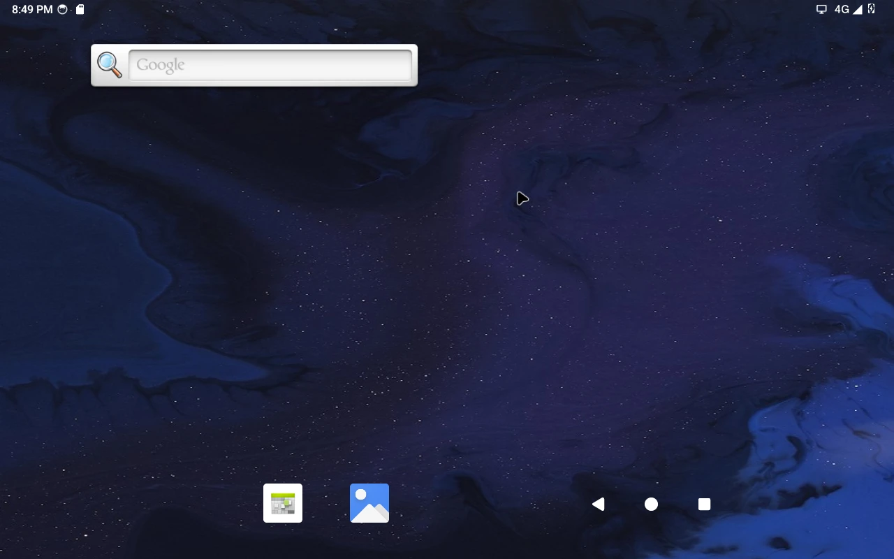
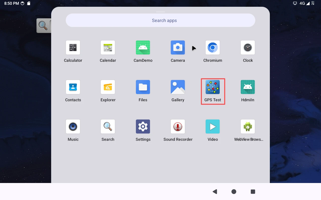
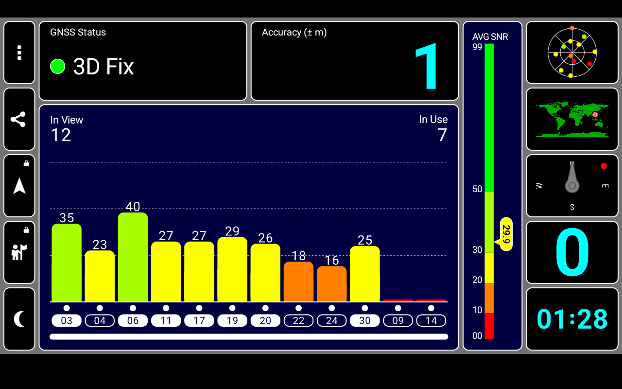
❸ Power on. Click GPS Test to test.
4.10 Audio
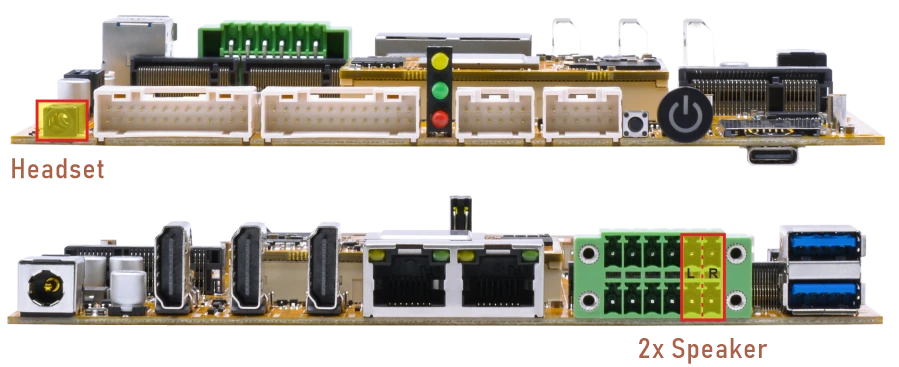
❶ Plug the Headset into the 3.5mm Audio jack.
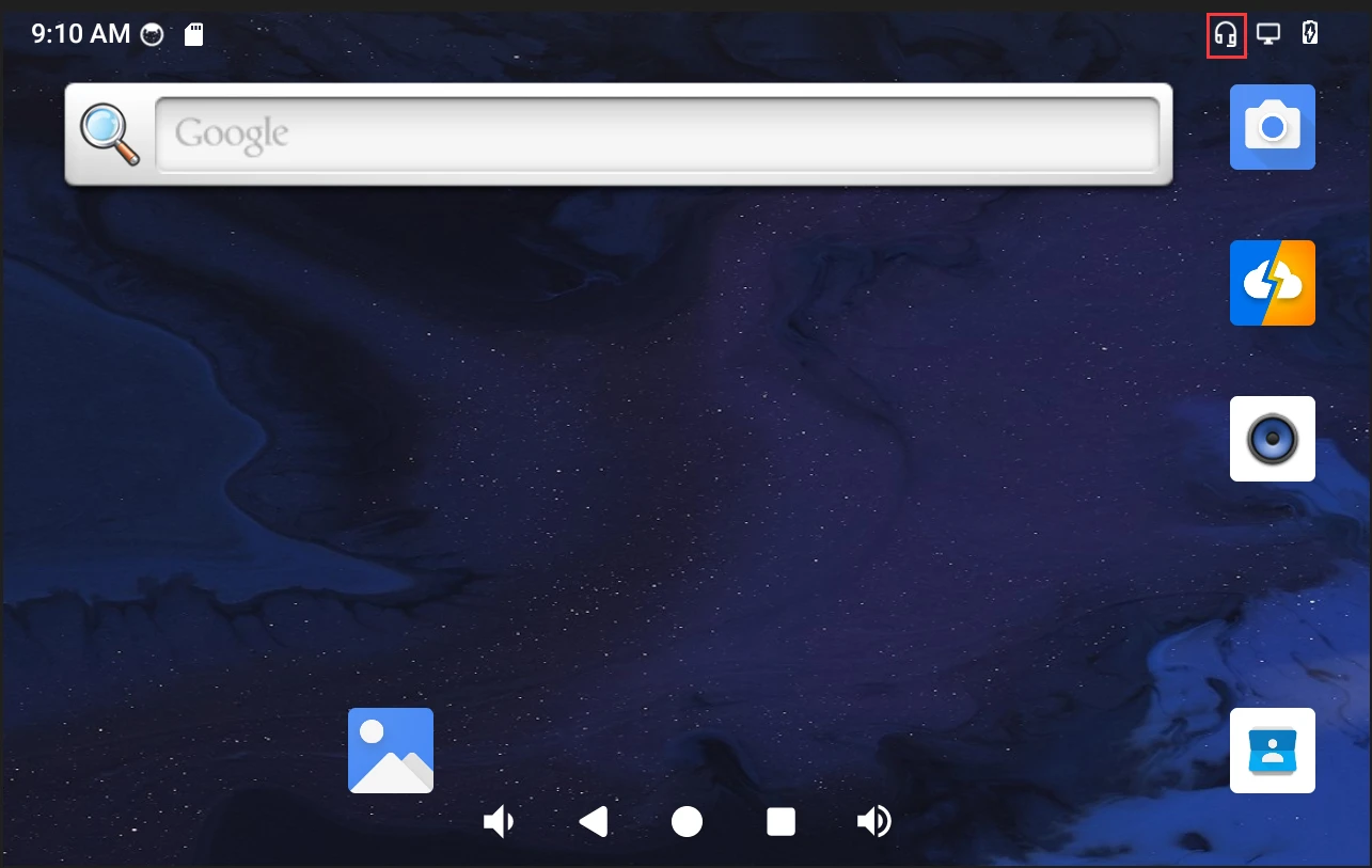
Headset insertion detected
❷ Open Sound Recorder
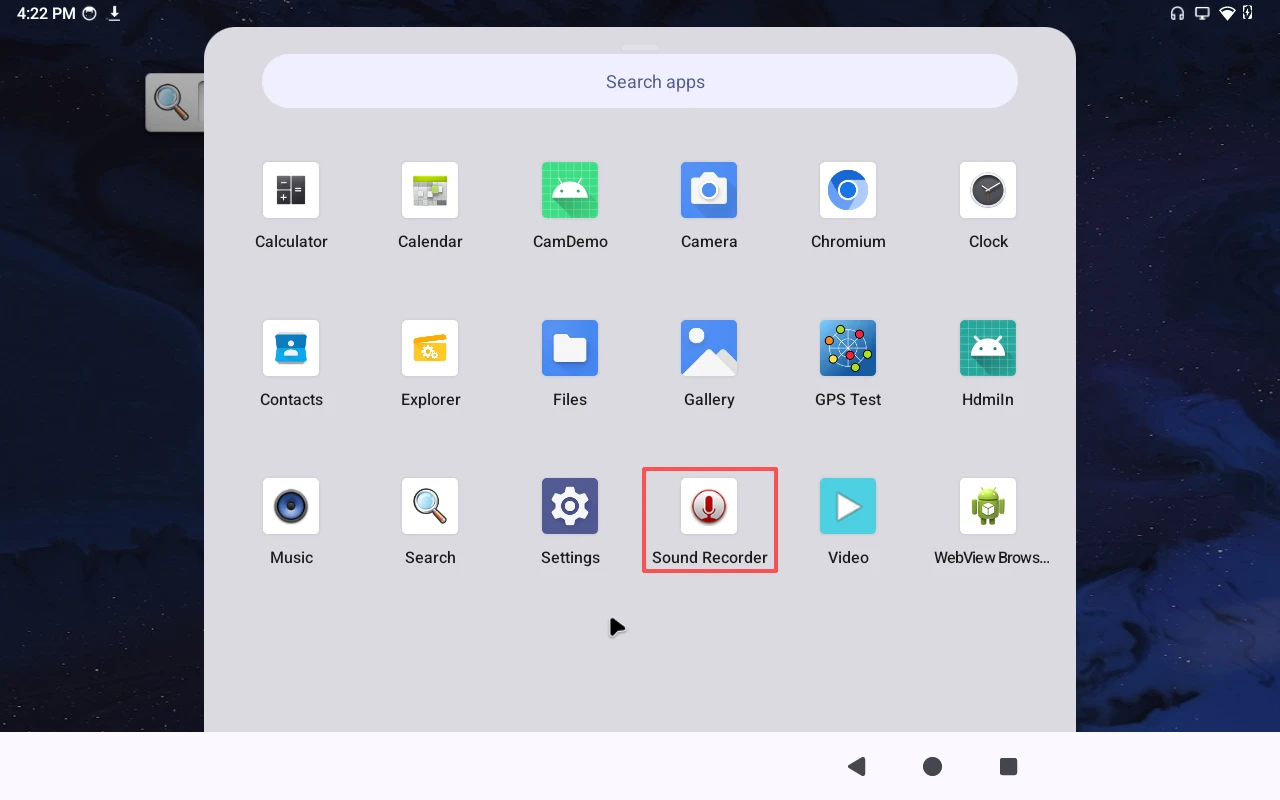
Record
❸ Click Start to start recording.
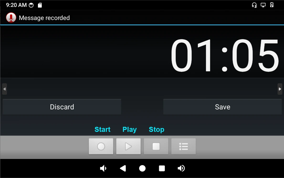
❹ After finish recording, click Stop -> play to test recorded file.
The headset jack supports both audio output and microphone input. For audio output, the headphone output has priority over the speaker output. When headphones are connected, the speaker output is disabled.
4.11 RTC
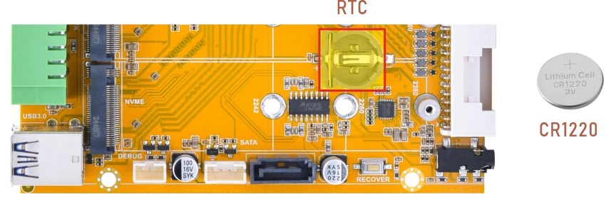
❶ Insert a 3V battery before test. It keeps the time running when the main power is off.
❷ Set date and time manually.
1su
2date -s "2026-05-28 16:56:00"            //set system date
3hwclock -w                              //set the hardware clock to current system time
4hwclock                                 //display date and time
console:/ # date -s "2026-05-28 16:56:00"
Thu May 28 16:56:00 GMT 2026
console:/ # hwclock -w
console:/ # hwclock
2026-05-28 16:56:42+0000
console:/ # hwclock
2026-05-28 16:56:43+0000
console:/ # hwclock
2026-05-28 16:56:44+0000
console:/ # hwclock
2026-05-28 16:56:44+0000
console:/ # hwclock
2026-05-28 16:56:45+0000
❸ Power off the board. Wait a while, then reapply power. If the RTC is functioning correctly, the clock should maintain its time and keep running while the board is powered off.
1hwclock
console:/ # hwclock
2026-05-28 17:04:54+0000
console:/ # hwclock
2026-05-28 17:04:55+0000
console:/ # hwclock
2026-05-28 17:04:59+0000
console:/ # hwclock
2026-05-28 17:05:01+0000
console:/ # hwclock
2026-05-28 17:05:03+0000
4.12 RS485
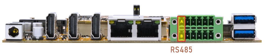
❶ Connect PC and board with USB-to-RS485 adapter.
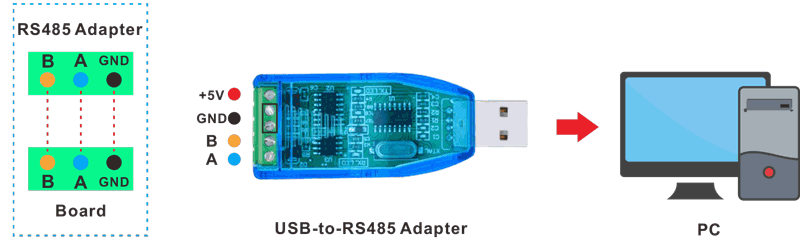
RS485 connection
❷ Open the Serial Terminal and set baud rate for RS485 adapter and development board respectively.
Baud rate: development board - 1500000; RS485 adapter - 115200
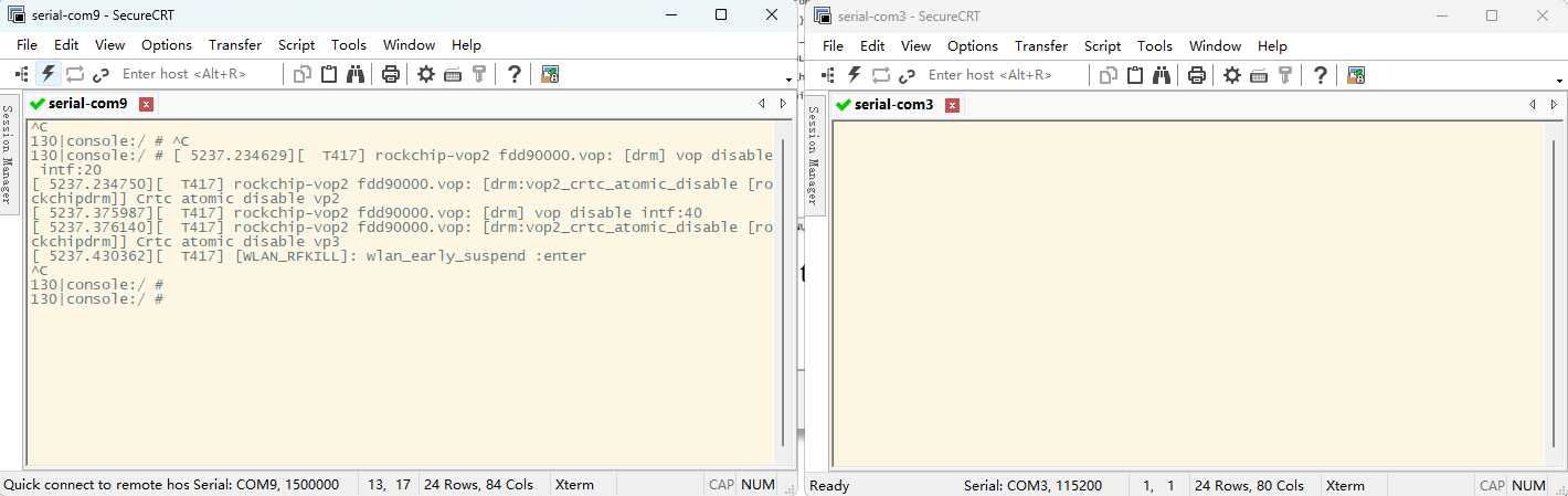
❸ Test RS485 reception.
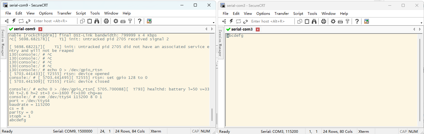
Run the following commands on the development board:
1echo 1 > /dev/gpio_rtsn
2com /dev/ttyS4 115200 8 0 1
Note
Because this image is based on GKI, automatic RS485 transmission/reception via software or hardware flow control is not possible. RS485 transmission/reception can only be achieved by manually controlling the RTSN signal.
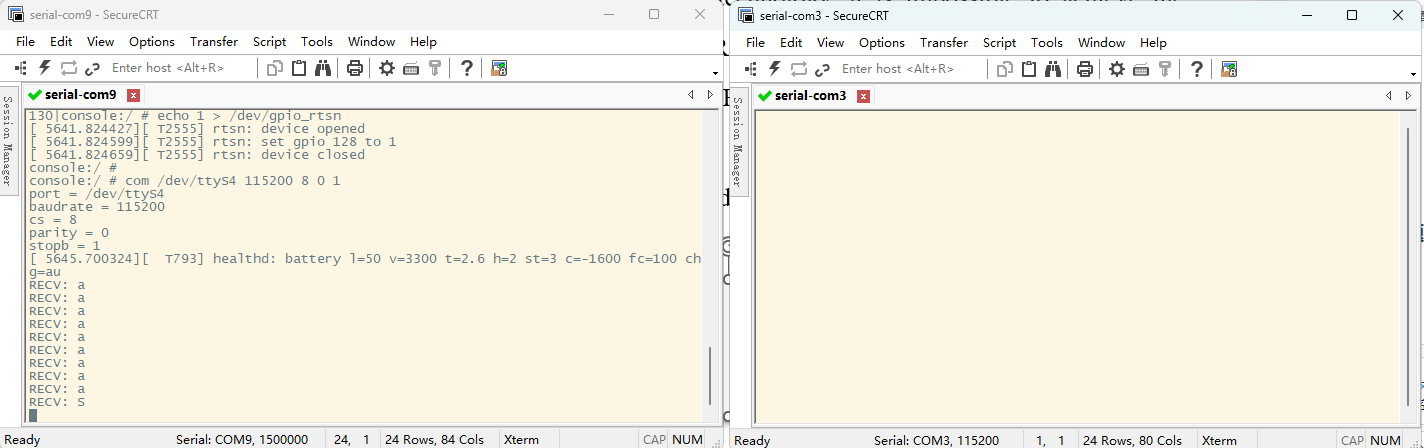
❹ Test RS485 transmission.
4.13 CAN
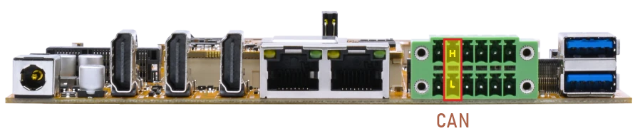
❶ Connect PC and board with USB-to-CAN adapter.
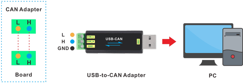
CAN connection
❷ Open the CAN application and set the baudrate to 500000 on PC.
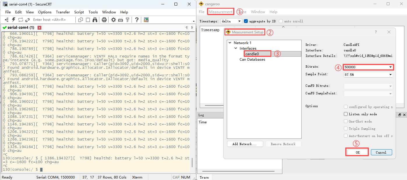
❸ Execute commands on Serial Terminal to configure CAN.
1su
2ip link set can0 down
3ip link set can0 type can bitrate 500000
4ip link set can0 up
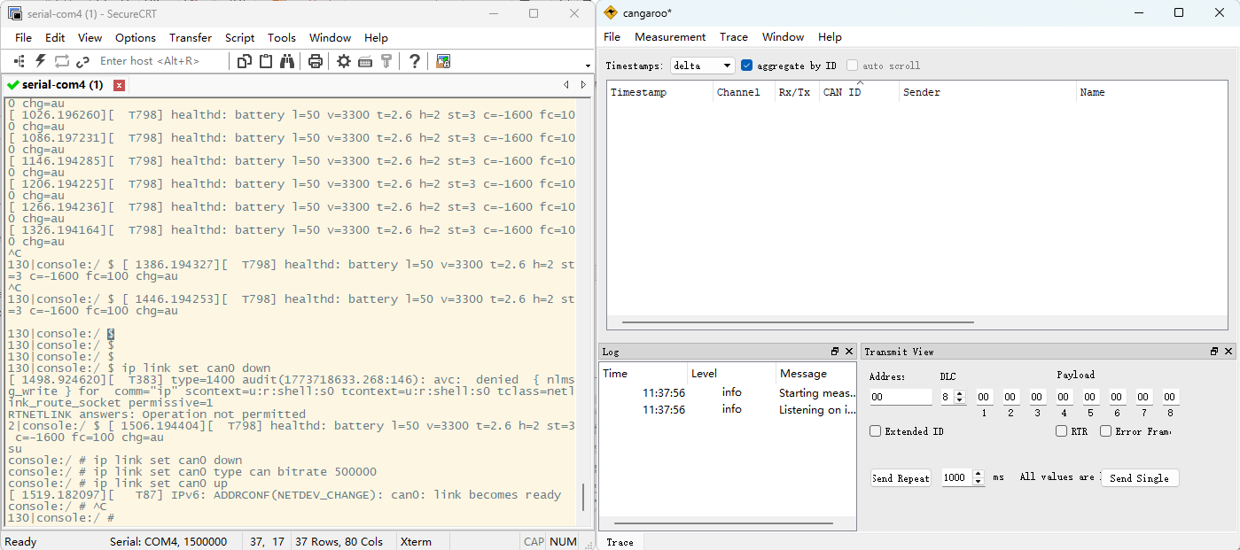
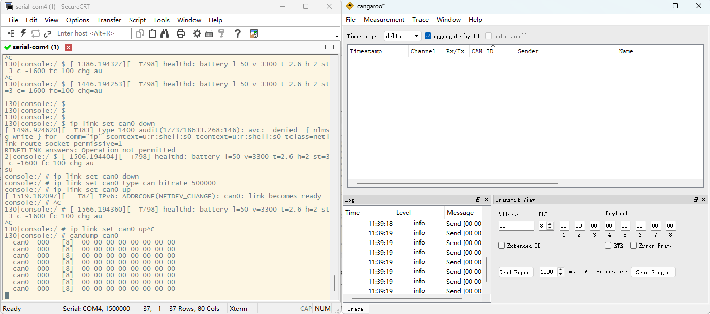
❹ Configure CAN as receiver.
1candump can0
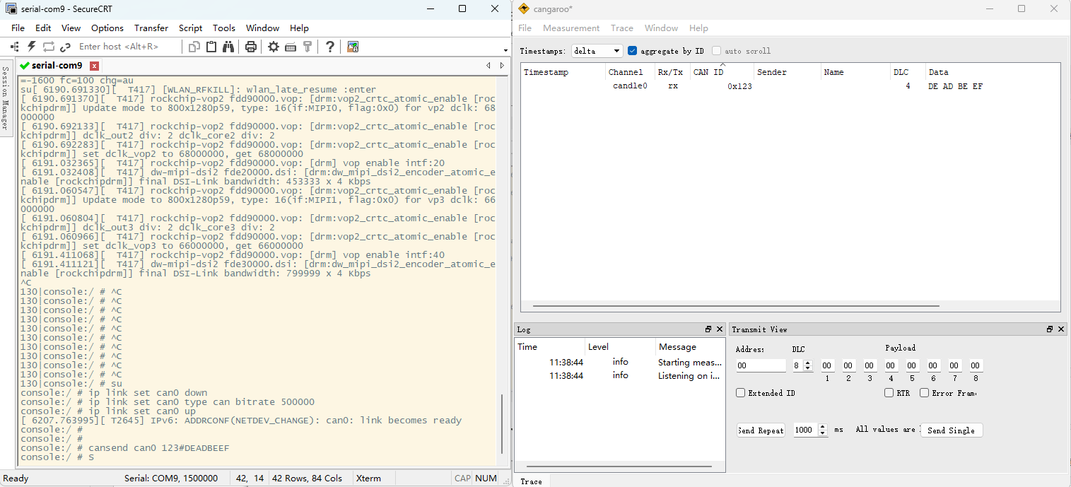
❺ Configure CAN as Transmitter.
1cansend can0 123#DEADBEEF
4.14 UART(RS232)
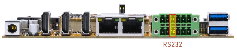
The UART loopback test is for reference only.
❶ Connect RX and TX of UART(RS232).
❷ Execute command and input character to test.
1com /dev/ttyS7 115200 8 0 1
console:/ $ com /dev/ttyS7 115200 8 0 1
port = /dev/ttyS7
baudrate = 115200
cs = 8
parity = 0
stopb = 1
123456789
RECV: 123456789
abcdefghijk
RECV: abcdefghijk
4.15 Camera
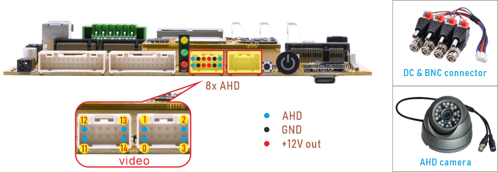
❶ Connect AHD camera to the development board.
❷ Preview.
Note
This device provides only a video capture interface. The preview function must be implemented by the customer through custom application development based on their specific requirements.
Single-camera preview, take video11 as an example:
1v4l2-ctl --verbose -d /dev/video11 --set-fmt-video=width=1920,height=1080,pixelformat='NV12' --stream-mmap=4 --set-selection=target=crop,flags=0,top=0,left=0,width=1920,height=1080 --stream-to=/mnt/out0.yuv
The file out0.yuv will be saved in /mnt/.
console:/ # ls /mnt/
androidwritable  expand     media_rw  out1_0.yuv    runtime  secure
appfuse          installer  obb       pass_through  scratch  user
asec             iso        out0.yuv  product       sdcard   vendor
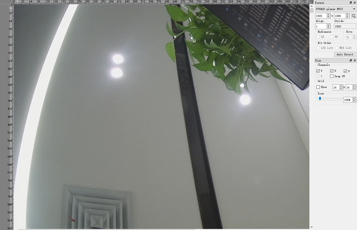
Copy the file to PC then play it with 7yuv