4. Android Application
4.1 Serial Terminal
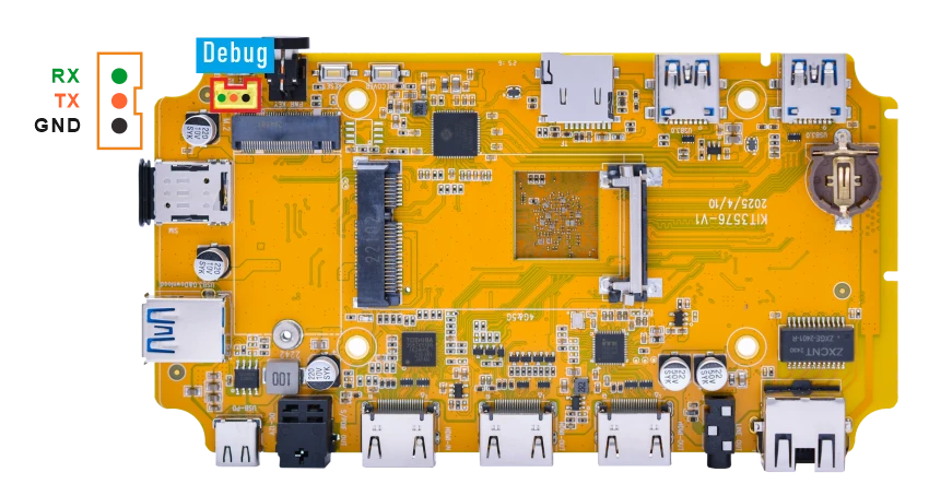
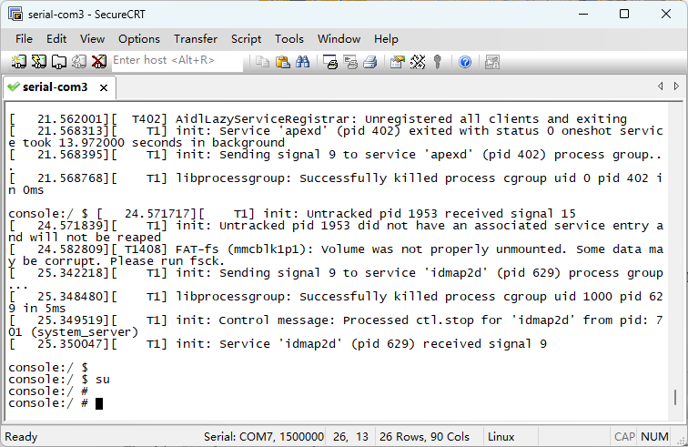
Connect the board and PC with USB Serial cable, then power on, the terminal will output boot information. The default baudrate is 1500000.
su //switch to root mode
4.2 Display

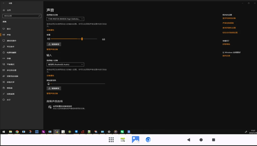
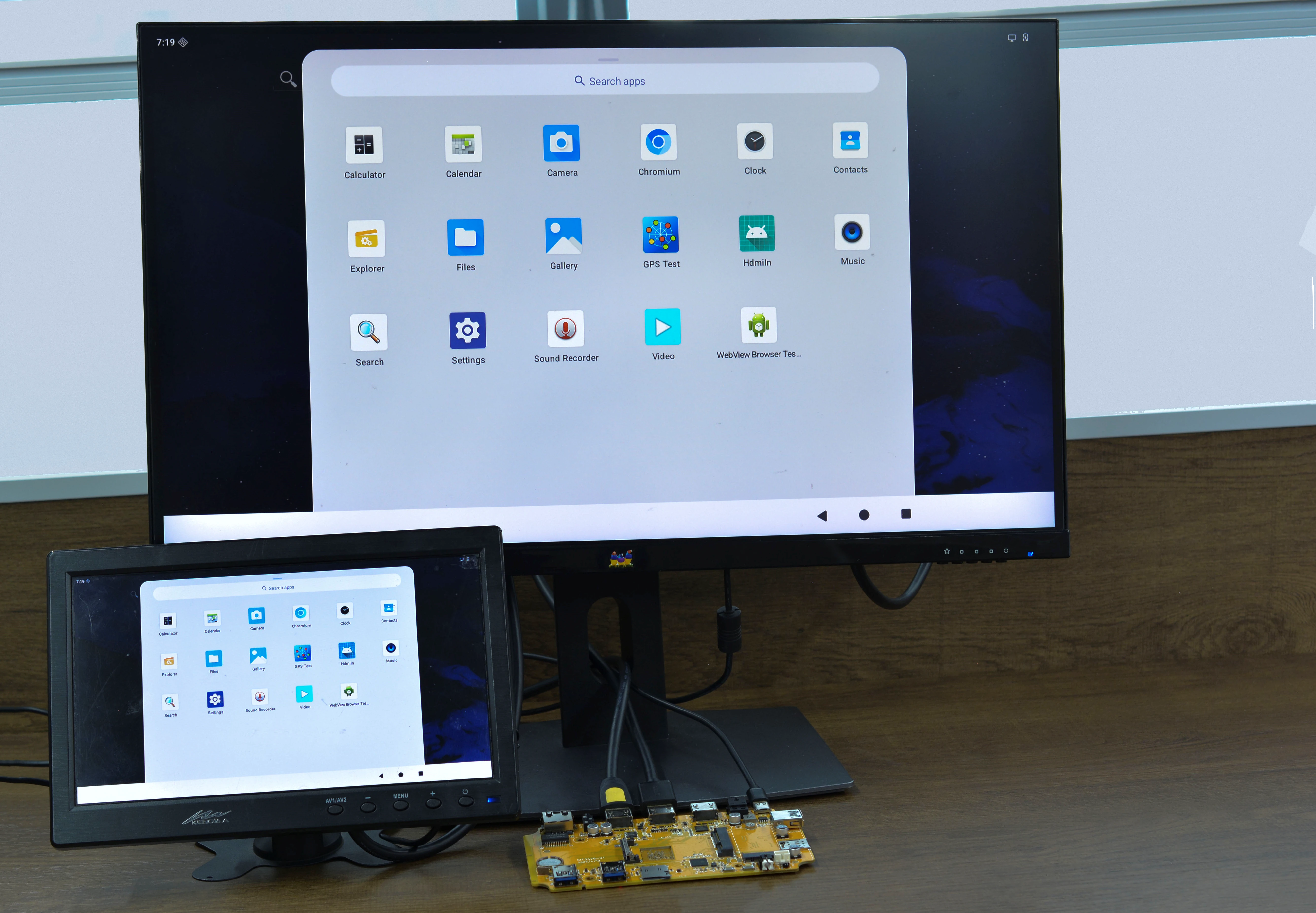
Compact3576 supports dual HDMI display synchronization.
4.3 USB
4.3.1 USB3.0 DRD
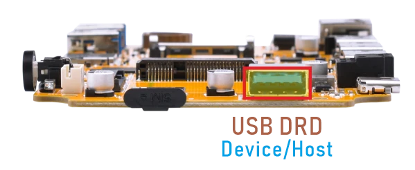
The Compact3576 USB3.0 DRD supports both Host and Device roles, with Device as the default configuration. ADB requires the USB3.0 port to be in Device mode.
ADB
❶ Connect the board and PC host with USB-A cable.
❷ Install ADB driver on Windows system.
❸ Press Windows + R to open the Run program. Type cmd and press Enter
❹ Execute the follow commands to enable ADB.
1adb root
2adb remount
3adb shell
USB3.0 Host
❶ Switch to USB Host mode.
1echo host > /sys/kernel/debug/usb/23000000.usb/mode
❷ After inserting the USB flash drive, it will be automatically mounted.
USB3.0 Superspeed detected[ 119.669348][ T15] usb 6-1: new SuperSpeed Gen 1 USB device number 2 using xhci-hcd [ 119.697584][ T15] usb 6-1: New USB device found, idVendor=0dd8, idProduct=3b00, bcdDevice= 0.02 [ 119.697700][ T15] usb 6-1: New USB device strings: Mfr=1, Product=2, SerialNumber=3 [ 119.697733][ T15] usb 6-1: Product: OnlyDisk [ 119.697758][ T15] usb 6-1: Manufacturer: Netac [ 119.697784][ T15] usb 6-1: SerialNumber: 0A6544CD10427AB2 [ 119.705999][ T15] usb-storage 6-1:1.0: USB Mass Storage device detected
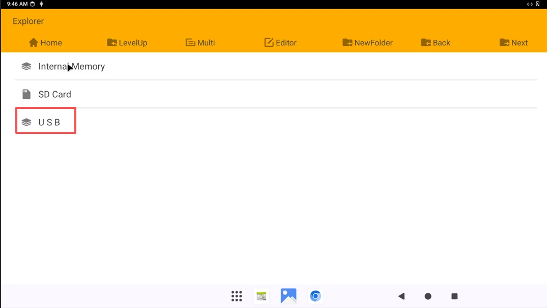
Switch USB3.0 DRD to USB device mode.
1echo device> /sys/kernel/debug/usb/23000000.usb/mode
4.3.2 USB3.0 Host
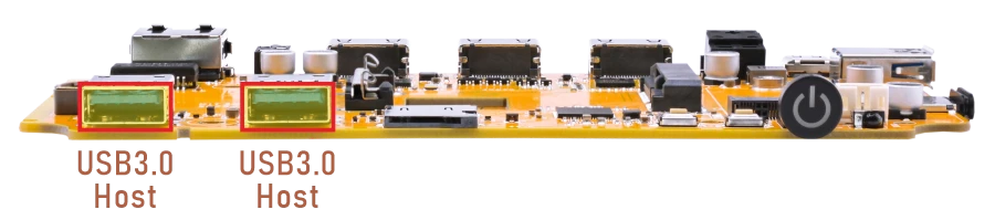
The USB3.0 Host can connect peripherals such as mouse, keyboards, and flash drives.
4.4 Ethernet

Connect the board and router with an Ethernet cable.
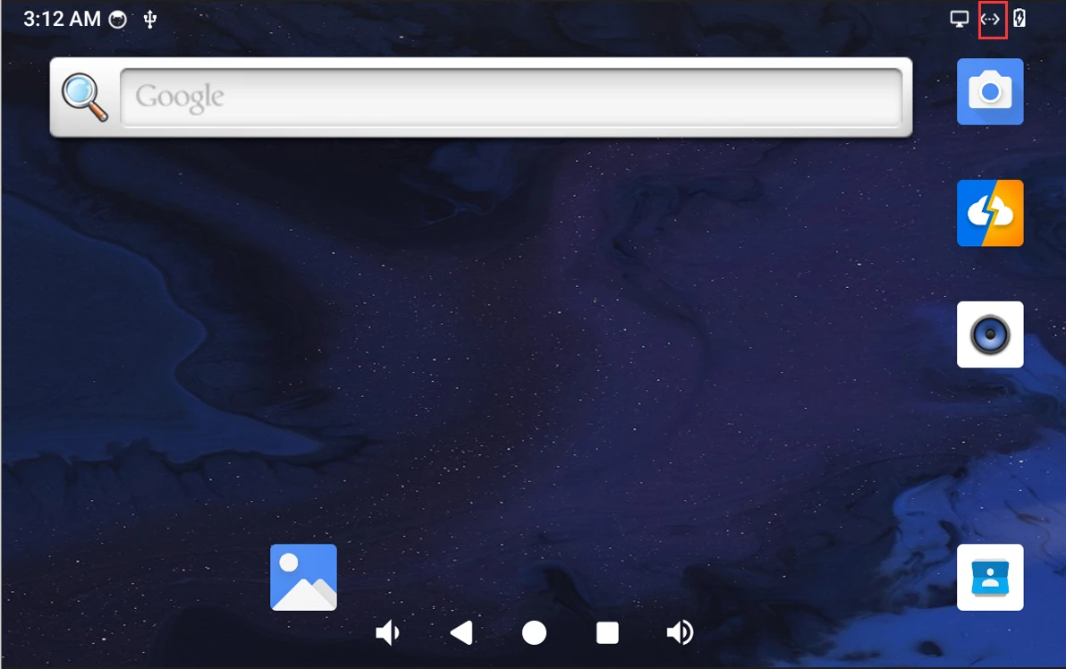
Network connected
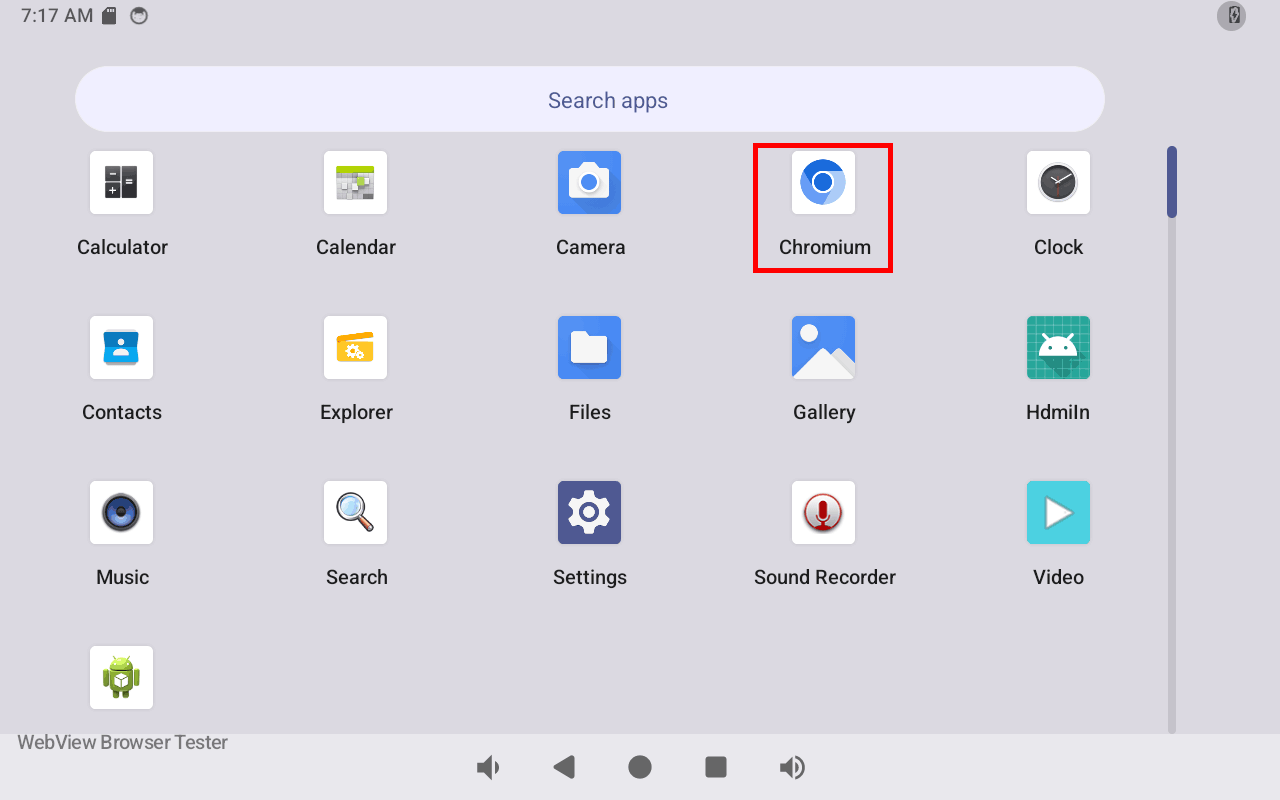
Open Chromium to test Network.
4.5 SD Card
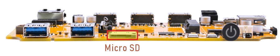
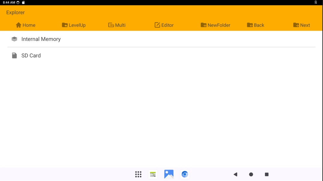
Compact3576 supports SD Hot-plug. Click Explorer to view the mounted SD card.
4.6 M.2(M-Key)
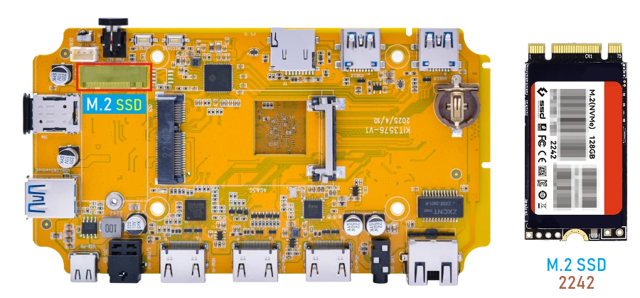
Connect SSD to the development board before power on. Click Explorer to view the device.
Execute the following commands to view the SSD node, it is mounted to the path /mnt/media_rw
1df -h
Attention
If the target device is not formatted with the ext4 file system, you must format it as ext4 before proceeding. This operation will permanently erase all existing data on the selected partition. Before running the command below, double‑check that the device path is correct.
1mke2fs -t ext4 /dev/block/nvme0n1p1
(Replace /dev/block/nvme0n1p1 with the actual partition on your device.)
4.7 WiFi & Bluetooth
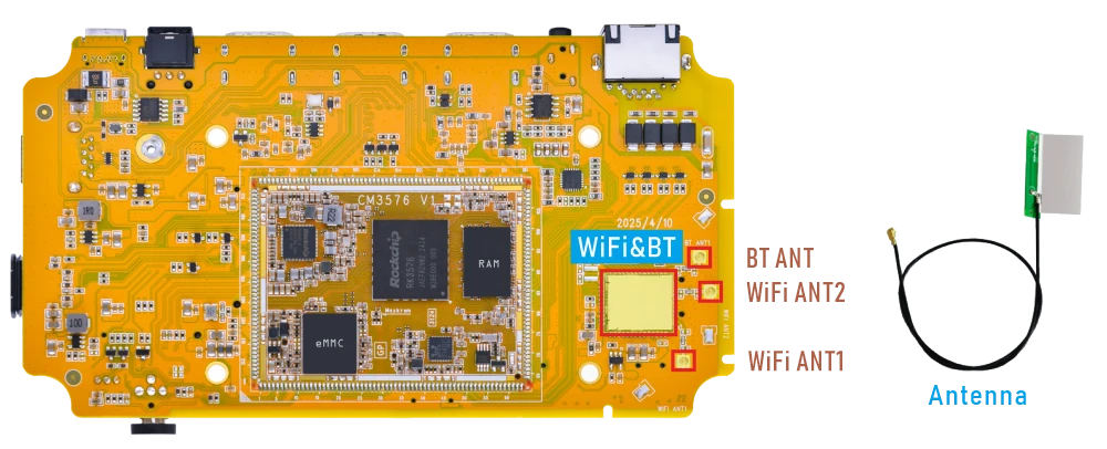
4.7.1 WiFi
❶ Connect the antennas.
❷ Click Settings -> Network & internet -> Internet -> Wi-Fi -> turn on
❸ Select the SSID from the list of available networks and enter the password.
After connected, open the browser Chromium or ping URL/IP at terminal to test Network.
1ifconfig
2ping -I wlan0 www.armdesigner.com
console:/ # ifconfig
eth0      Link encap:Ethernet  HWaddr be:c3:37:8b:f1:c4  Driver rk_gmac-dwmac
          inet addr:192.168.0.224  Bcast:192.168.0.255  Mask:255.255.255.0
          inet6 addr: fe80::e5c7:2a06:b4df:2afd/64 Scope: Link
          UP BROADCAST RUNNING MULTICAST  MTU:1500  Metric:1
          RX packets:473 errors:0 dropped:0 overruns:0 frame:0
          TX packets:70 errors:0 dropped:0 overruns:0 carrier:0
          collisions:0 txqueuelen:1000
          RX bytes:50096 TX bytes:8775
          Interrupt:83
console:/ #
console:/ # ping -I wlan0 www.armdesigner.com
PING www.armdesigner.com (67.222.54.196) from 192.168.0.144 wlan0: 56(84) bytes of data.
64 bytes from 67-222-54-196.unifiedlayer.com (67.222.54.196): icmp_seq=1 ttl=48 time=196 ms
64 bytes from 67-222-54-196.unifiedlayer.com (67.222.54.196): icmp_seq=2 ttl=48 time=189 ms
64 bytes from 67-222-54-196.unifiedlayer.com (67.222.54.196): icmp_seq=3 ttl=48 time=189 ms
64 bytes from 67-222-54-196.unifiedlayer.com (67.222.54.196): icmp_seq=4 ttl=48 time=225 ms
64 bytes from 67-222-54-196.unifiedlayer.com (67.222.54.196): icmp_seq=5 ttl=48 time=248 ms
^C
--- www.armdesigner.com ping statistics ---
5 packets transmitted, 5 received, 0% packet loss, time 4464ms
rtt min/avg/max/mdev = 189.233/209.876/248.002/23.195 ms
console:/ #
4.7.2 Bluetooth
Click Settings -> Connected devices -> Pair new device
Select the available device in the list to pair.
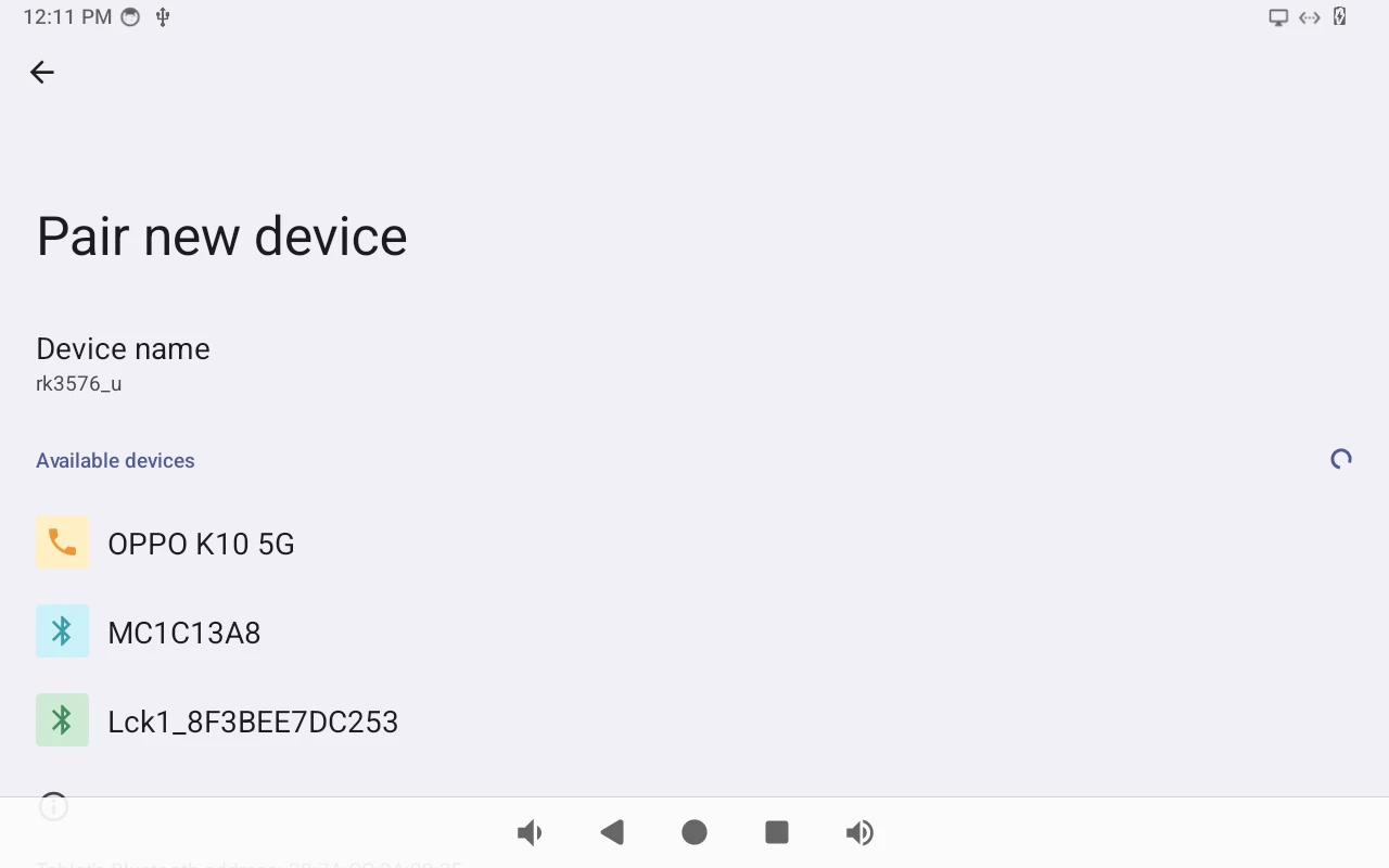
After pairing, devices can connect with each other automatically.
4.8 4G & GPS
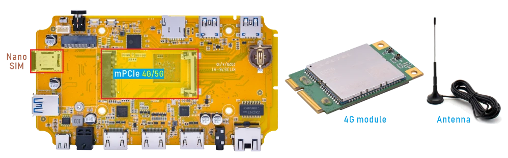
4.8.1 4G
❶ Insert 4G module to mPCIe slot (4G model: EC20).
❷ Connect antenna and insert SIM card.
❸ Power on. The default connection is 4G network.
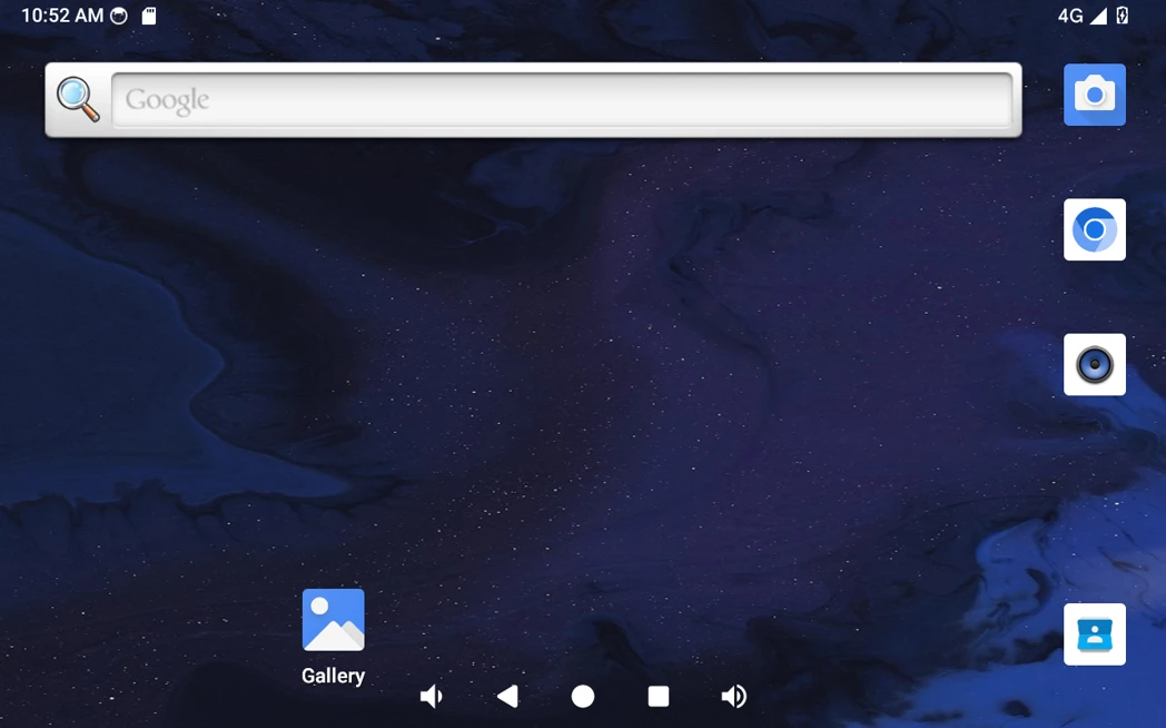
4G network
Open the browser or ping URL/IP at terminal to test Network.
1ifconfig
2ping -I wwan0 www.armdesigner.com
console:/ # ifconfig
wwan0     Link encap:Ethernet  HWaddr 2e:0a:be:d3:db:86  Driver qmi_wwan_q
          inet addr:10.79.15.253  Mask:255.255.255.252
          inet6 addr: fe80::2c0a:beff:fed3:db86/64 Scope: Link
          UP RUNNING NOARP  MTU:1500  Metric:1
          RX packets:19 errors:0 dropped:0 overruns:0 frame:0
          TX packets:20 errors:0 dropped:0 overruns:0 carrier:0
          collisions:0 txqueuelen:1000
          RX bytes:2108 TX bytes:2213

console:/ # ping -I wwan0 www.armdesigner.com
PING www.armdesigner.com (67.222.54.196) from 10.96.137.126 wwan0: 56(84) bytes of data.
64 bytes from 67-222-54-196.unifiedlayer.com (67.222.54.196): icmp_seq=1 ttl=47 time=220 ms
64 bytes from 67-222-54-196.unifiedlayer.com (67.222.54.196): icmp_seq=2 ttl=47 time=209 ms
64 bytes from 67-222-54-196.unifiedlayer.com (67.222.54.196): icmp_seq=3 ttl=47 time=213 ms
64 bytes from 67-222-54-196.unifiedlayer.com (67.222.54.196): icmp_seq=4 ttl=47 time=208 ms
64 bytes from 67-222-54-196.unifiedlayer.com (67.222.54.196): icmp_seq=5 ttl=47 time=208 ms
64 bytes from 67-222-54-196.unifiedlayer.com (67.222.54.196): icmp_seq=6 ttl=47 time=208 ms
64 bytes from 67-222-54-196.unifiedlayer.com (67.222.54.196): icmp_seq=7 ttl=47 time=207 ms
^C
--- www.armdesigner.com ping statistics ---
7 packets transmitted, 7 received, 0% packet loss, time 6002ms
rtt min/avg/max/mdev = 207.607/210.826/220.234/4.316 ms
4.8.2 GPS
❶ Insert 4G module to mPCIe socket.
❷ Connect GPS antenna.
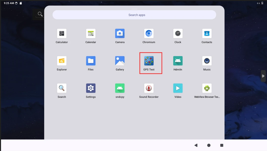
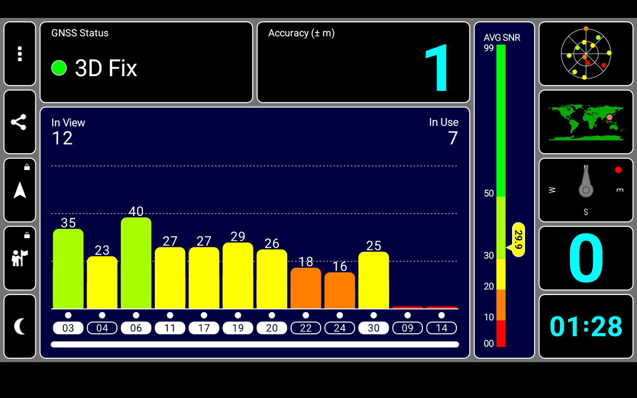
❸ Power on. Click GPS Test to test.
4.9 Audio

4.9.1 Headphone
❶ Plug the Headphone into the 3.5mm Audio jack.
❷ Check the sound card ID.
1cat /proc/asound/cards
console:/ # cat /proc/asound/cards
 0 [rockchipes8390 ]: rockchip-es8390 - rockchip-es8390
                      rockchip-es8390
 1 [rkhdmiintc35874]: simple-card - rk,hdmiin-tc358749x-codec
                      rk,hdmiin-tc358749x-codec
 2 [rockchipspdiftx]: simple-card - rockchip,spdif-tx0
                      rockchip,spdif-tx0
 3 [rockchipdp0    ]: rockchip-dp0 - rockchip-dp0
                      rockchip-dp0
 4 [rockchiphdmi   ]: rockchip-hdmi - rockchip-hdmi
                      rockchip-hdmi
❸ Playback.
1aplay -Dhw:0,0 test.wav
aplay -Dhw:2,0 test.wav   //S/PDIF out audio output
aplay -Dhw:3,0 test.wav   //DP AIT mode audio output
aplay -Dhw:4,0 test.wav   //HDMI TX audio output
4.9.2 SPDIF OUT
❶ Connect SPDIF OUT to receiver’s SPDIF IN.
❷ Set source audio output to SPDIF.
❸ Check the sound card ID.
1cat /proc/asound/cards
console:/ # cat /proc/asound/cards
 0 [rockchipes8390 ]: rockchip-es8390 - rockchip-es8390
                      rockchip-es8390
 1 [rkhdmiintc35874]: simple-card - rk,hdmiin-tc358749x-codec
                      rk,hdmiin-tc358749x-codec
 2 [rockchipspdiftx]: simple-card - rockchip,spdif-tx0
                      rockchip,spdif-tx0
 3 [rockchipdp0    ]: rockchip-dp0 - rockchip-dp0
                      rockchip-dp0
 4 [rockchiphdmi   ]: rockchip-hdmi - rockchip-hdmi
                      rockchip-hdmi
❹ Playback.
1aplay -Dhw:2,0 test.wav
4.10 RTC
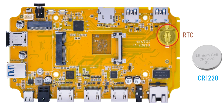
❶ Insert a 3V battery before test. It keeps the time running when the main power is off.
❷ Set date and time manually.
1date -s "2026-05-28 16:56:00"            //set system date
2hwclock -w                              //set the hardware clock to current system time
3hwclock                                 //display date and time
console:/ # date -s "2026-05-28 16:56:00"
Thu May 28 16:56:00 GMT 2026
console:/ # hwclock -w
console:/ # hwclock
2026-05-28 16:56:42+0000
console:/ # hwclock
2026-05-28 16:56:43+0000
console:/ # hwclock
2026-05-28 16:56:44+0000
console:/ # hwclock
2026-05-28 16:56:44+0000
console:/ # hwclock
2026-05-28 16:56:45+0000
❸ Power off. Wait for a moment, power on again, and then execute the command hwclock, you will find that the time is saved.
console:/ # hwclock
2026-05-28 17:04:54+0000
console:/ # hwclock
2026-05-28 17:04:55+0000
console:/ # hwclock
2026-05-28 17:04:59+0000
console:/ # hwclock
2026-05-28 17:05:01+0000
console:/ # hwclock
2026-05-28 17:05:03+0000
If connected to the internet, the time will automatically synchronize with the network time.
4.11 IR

❶ Open IR debugging print.
1echo 1 > /sys/module/rockchip_pwm_remotectl/parameters/code_print
❷ Press the Infrared controller, you can view the received datas on the terminal.
console:/ # echo 1 > /sys/module/rockchip_pwm_remotectl/parameters/code_print
[ 3455.141358][    C1] USERCODE=0xb24d
[ 3455.167518][    C1] RMC_GETDATA=2
[ 3456.206876][    C1] USERCODE=0xb24d
[ 3456.233033][    C1] RMC_GETDATA=2
[ 3456.300413][    C1] USERCODE=0xb24d
[ 3456.326573][    C1] RMC_GETDATA=2
[ 3457.927422][    C1] USERCODE=0xb24d
[ 3457.953580][    C1] RMC_GETDATA=2
[ 3458.020950][    C1] USERCODE=0xb24d
[ 3458.047108][    C1] RMC_GETDATA=2
[ 3459.012683][    C1] USERCODE=0xb24d
[ 3459.038839][    C1] RMC_GETDATA=2
[ 3459.106130][    C1] USERCODE=0xb24d
[ 3459.132361][    C1] RMC_GETDATA=2
4.12 Video Play
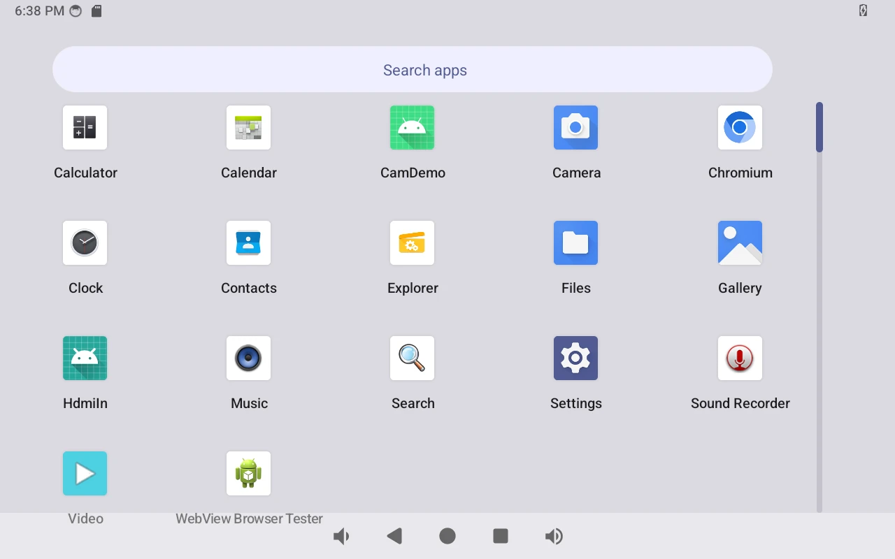
❶ Click Video.
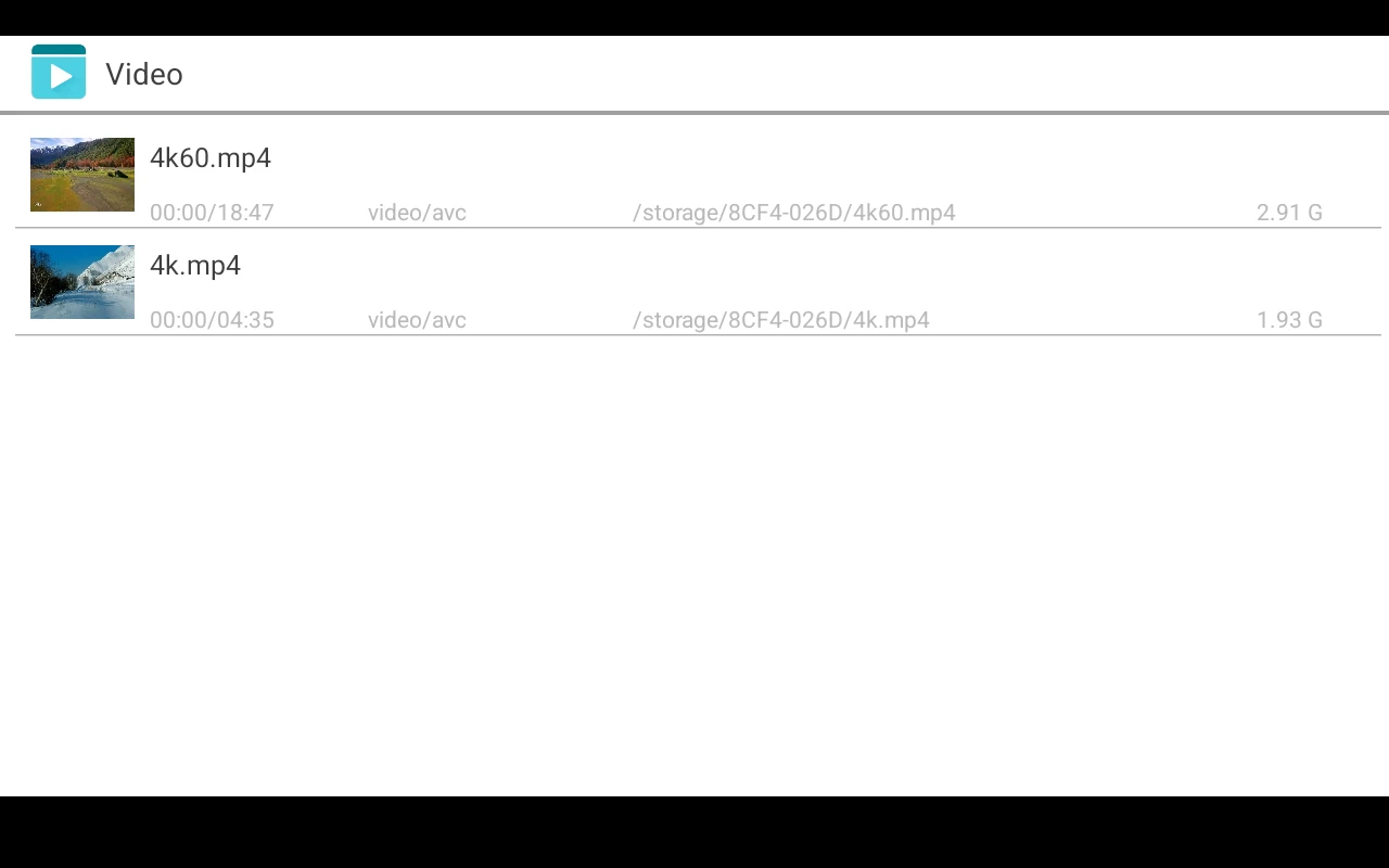
❷ Select video file to play.
Note
The Compact3576 supports video playback up to 4K at 60Hz and decodes VP8, H.264, H.265, VP9, and AV1. However, H.265 playback is limited to specific encoding profiles and may not support all variants.
4.13 HDMI IN

❶ Connect the output device’s HDMI_OUT to the Compact3576’s HDMI_IN, and the Compact3576’s HDMI_OUT to the HDMI monitor, then power on. The log will show:
[ 36.800368][ T165] m03_b_tc35874x 4-000f: tc35874x_format_change: New format: 1920x1080p60.00 (2200x1125)
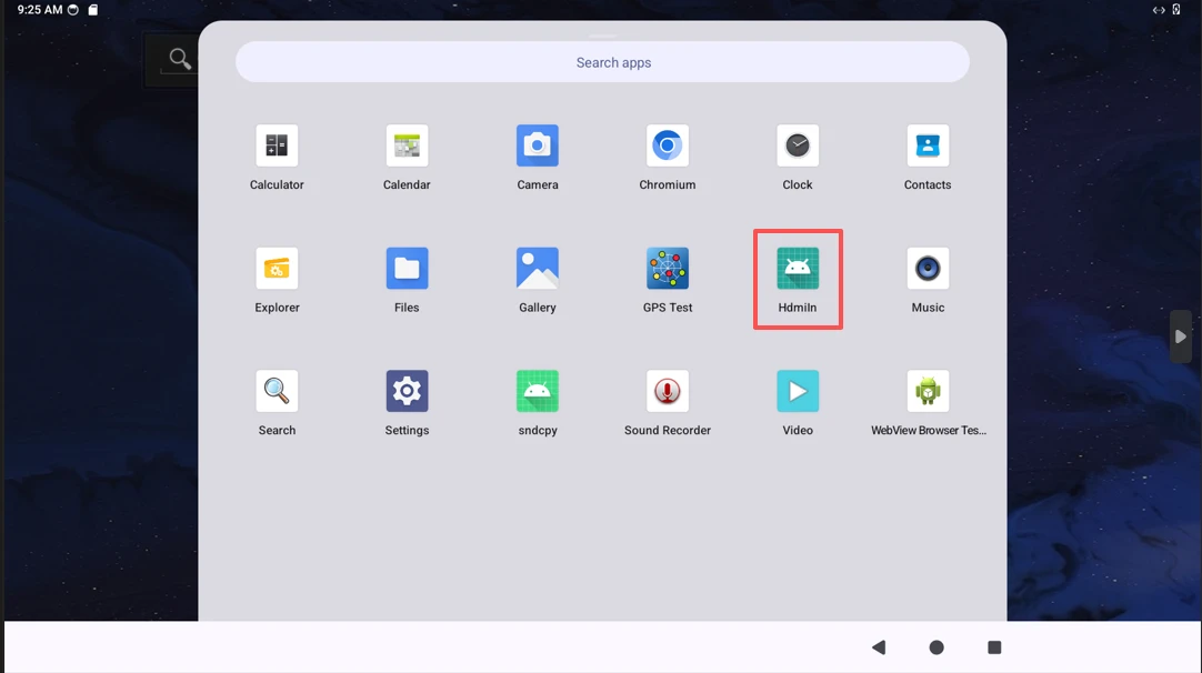
❷ Open HdmiIn to preview the video input.