4. Android Application
4.1 Serial Terminal
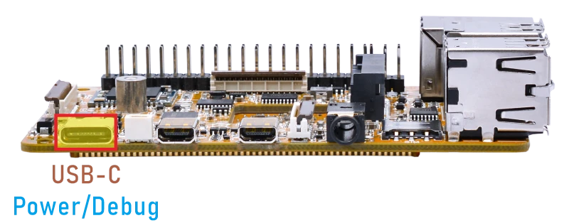
Connect the board to the PC via a USB-C cable, and open a serial terminal with the baud rate set to 1500000. The boot log will appear on the terminal.
su //switch to root mode
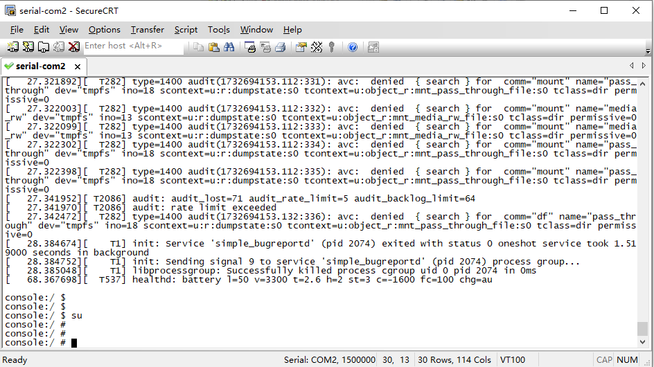
Serial Terminal
4.2 Display
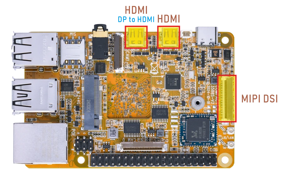
Compact3588S supports MIPI LCD, HDMI and DP-to-HDMI display synchronization.
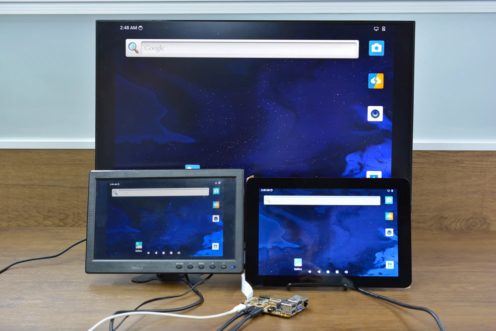
4.3 USB
4.3.1 USB3.0
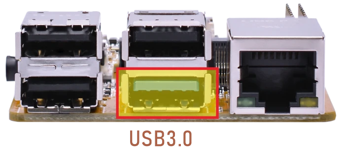
The Compact3588S USB3.0 supports both Host and Device roles. ADB requires the USB3.0 port to be in Device mode.
ADB
❶ Connect the board and PC host with USB-A cable.
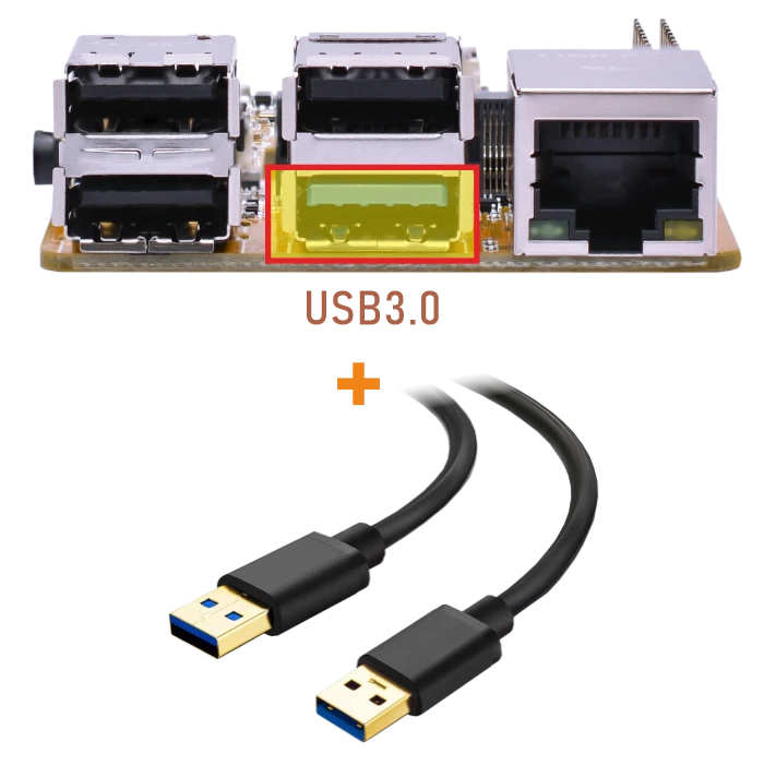
❷ Install ADB driver on Windows system.
❸ Press Windows + R to open the Run program. Type cmd and press Enter
❹ Execute the follow commands to enable ADB.
1adb root
2adb remount
3adb shell
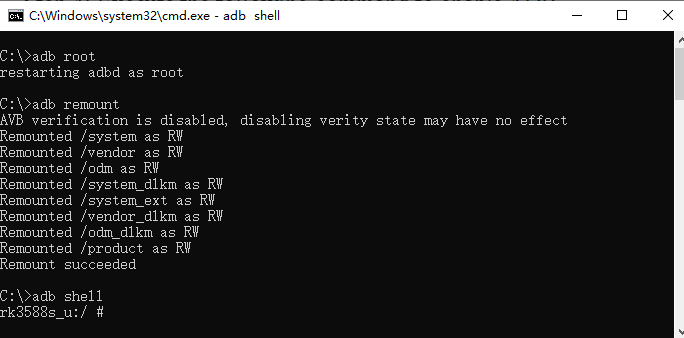
enable ADB
USB3.0 Host
❶ Switch the USB Host mode on the serial port CLI.
1echo host > /sys/kernel/debug/usb/fc000000.usb/mode
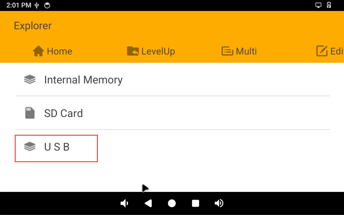
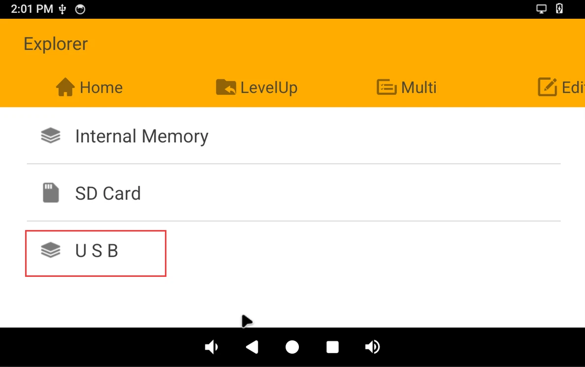
❷ After inserting the USB flash drive, it will be automatically mounted.
USB3.0 Superspeed detected[ 119.669348][ T15] usb 6-1: new SuperSpeed Gen 1 USB device number 2 using xhci-hcd [ 119.697584][ T15] usb 6-1: New USB device found, idVendor=0dd8, idProduct=3b00, bcdDevice= 0.02 [ 119.697700][ T15] usb 6-1: New USB device strings: Mfr=1, Product=2, SerialNumber=3 [ 119.697733][ T15] usb 6-1: Product: OnlyDisk [ 119.697758][ T15] usb 6-1: Manufacturer: Netac [ 119.697784][ T15] usb 6-1: SerialNumber: 0A6544CD10427AB2 [ 119.705999][ T15] usb-storage 6-1:1.0: USB Mass Storage device detected
4.3.2 USB2.0
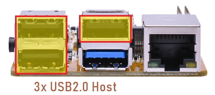
The USB2.0 Host can connect peripherals such as mouse, keyboards, and flash drives.
4.4 Ethernet
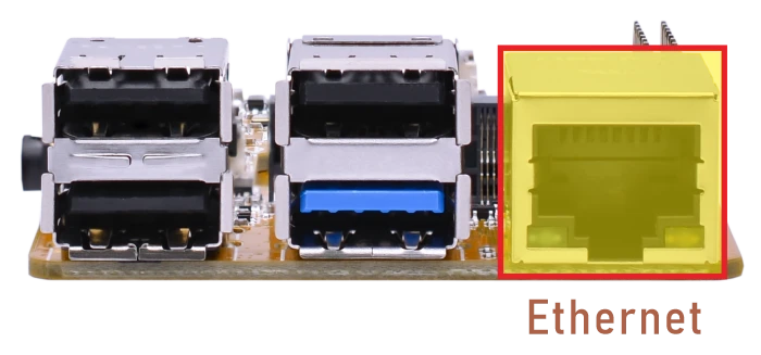
Connect the board and router with an Ethernet cable.
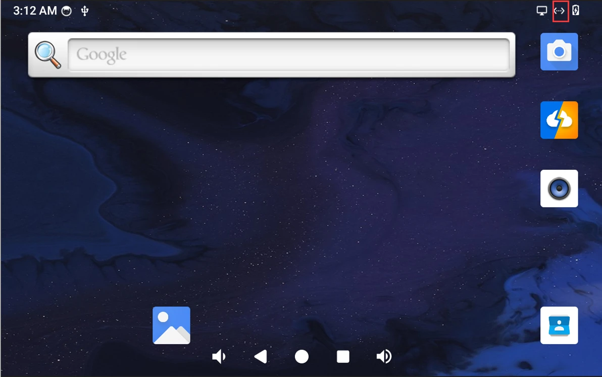
Network connected
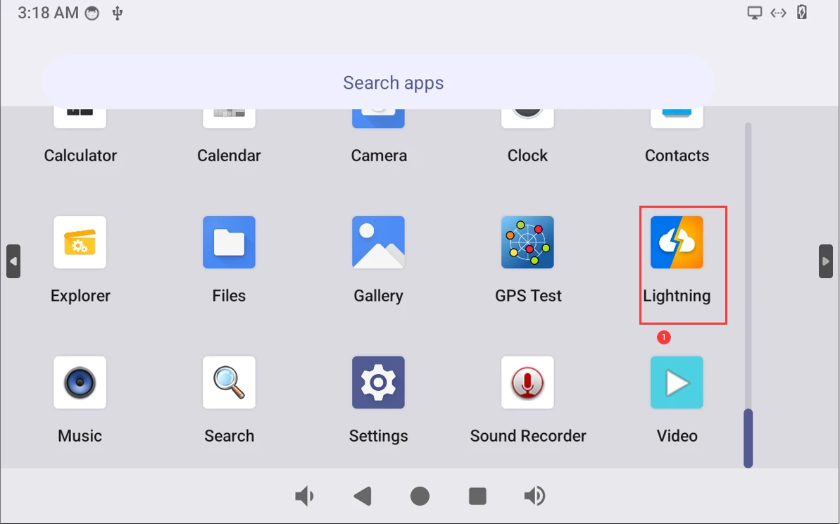
Open Lighting (browser) to test Network.
4.5 WiFi & Bluetooth
4.5.1 WiFi
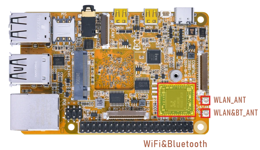
❶ Connect the antennas.
❷ Click Settings -> Network & internet -> Internet -> Wi-Fi -> turn on
❸ Select the SSID from the list of available networks and enter the password.
After connected, open the browser or ping URL/IP at terminal to test Network.
browser
1su
2ifconfig
3ping -I wlan0 www.armdesigner.com
console:/ $ su
console:/ # ifconfig
wlan0     Link encap:Ethernet  HWaddr d4:9c:dd:f5:e7:22
       inet addr:192.168.0.141  Bcast:192.168.0.255  Mask:255.255.255.0
       inet6 addr: fe80::4f11:385d:e067:a512/64 Scope: Link
       UP BROADCAST RUNNING MULTICAST  MTU:1500  Metric:1
       RX packets:869 errors:0 dropped:0 overruns:0 frame:0
       TX packets:1362 errors:0 dropped:0 overruns:0 carrier:0
       collisions:0 txqueuelen:1000
       RX bytes:174072 TX bytes:196964
console:/ # ping -I wlan0 www.armdesigner.com
PING www.armdesigner.com (67.222.54.196) from 192.168.0.141 wlan0: 56(84) bytes of data.
64 bytes from 67-222-54-196.unifiedlayer.com (67.222.54.196): icmp_seq=1 ttl=48 time=183 ms
64 bytes from 67-222-54-196.unifiedlayer.com (67.222.54.196): icmp_seq=2 ttl=48 time=184 ms
64 bytes from 67-222-54-196.unifiedlayer.com (67.222.54.196): icmp_seq=3 ttl=48 time=209 ms
64 bytes from 67-222-54-196.unifiedlayer.com (67.222.54.196): icmp_seq=4 ttl=48 time=185 ms
64 bytes from 67-222-54-196.unifiedlayer.com (67.222.54.196): icmp_seq=5 ttl=48 time=187 ms
64 bytes from 67-222-54-196.unifiedlayer.com (67.222.54.196): icmp_seq=6 ttl=48 time=185 ms
64 bytes from 67-222-54-196.unifiedlayer.com (67.222.54.196): icmp_seq=7 ttl=48 time=185 ms
64 bytes from 67-222-54-196.unifiedlayer.com (67.222.54.196): icmp_seq=8 ttl=48 time=186 ms
^C
--- www.armdesigner.com ping statistics ---
8 packets transmitted, 8 received, 0% packet loss, time 7006ms
rtt min/avg/max/mdev = 183.650/188.586/209.785/8.114 ms
4.5.2 Bluetooth
Click Settings -> Connected devices -> Pair new device
Select the available device in the list to pair.
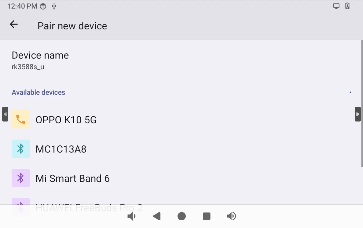
After pairing, devices can connect with each other automatically.
4.6 UART
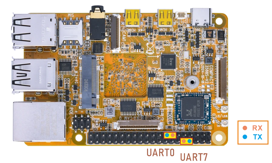
❶ Connect RX and TX of UART.
❷ Execute command and input character to test.
1com /dev/ttyS0 115200 8 0 1 //UART0
console:/ # com /dev/ttyS0 115200 8 0 1
port = /dev/ttyS0
baudrate = 115200
cs = 8
parity = 0
stopb = 1
1234567890abc
RECV: 1234567890abc
The tests for UART7 are similar to those for UART0. Simply replace ttyS0 with ttyS7.
com /dev/ttyS7 115200 8 0 1
4.7 4G
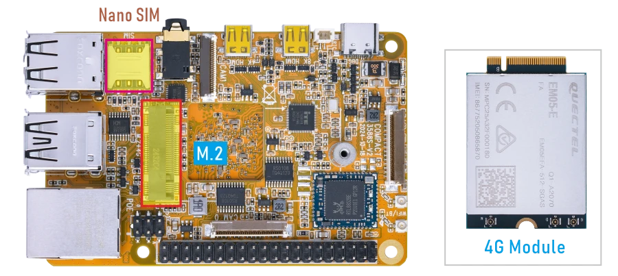
❶ Insert 4G module to M.2 slot (4G model: EM05).
❷ Connect antenna and insert SIM card.
❸ Power on. The default connection is 4G network.
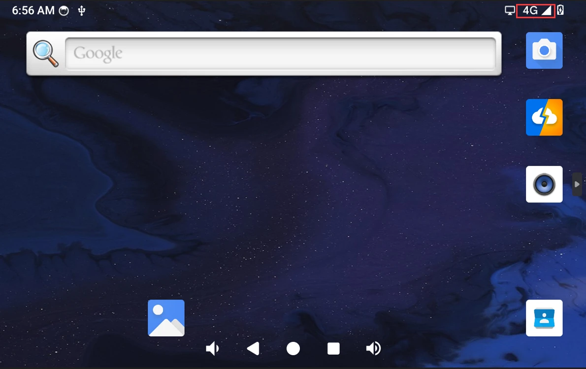
4G network
Open the browser or ping URL/IP at terminal to test Network.
1su
2ifconfig
3ping -I wwan0 www.armdesigner.com
console:/ $ su
console:/ # ifconfig
wwan0     Link encap:Ethernet  HWaddr 82:6a:80:51:1e:5e  Driver qmi_wwan_q
       inet addr:10.165.83.73  Mask:255.255.240.0
       inet6 addr: fe80::806a:80ff:fe51:1e5e/64 Scope: Link
       UP RUNNING NOARP  MTU:1500  Metric:1
       RX packets:379 errors:0 dropped:0 overruns:0 frame:0
       TX packets:751 errors:0 dropped:0 overruns:0 carrier:0
       collisions:0 txqueuelen:1000
       RX bytes:131898 TX bytes:111306

console:/ # ping -I wwan0 www.armdesigner.com
PING www.armdesigner.com (67.222.54.196) from 10.165.83.73 wwan0: 56(84) bytes of data.
64 bytes from 67-222-54-196.unifiedlayer.com (67.222.54.196): icmp_seq=1 ttl=46 time=285 ms
64 bytes from 67-222-54-196.unifiedlayer.com (67.222.54.196): icmp_seq=2 ttl=46 time=308 ms
64 bytes from 67-222-54-196.unifiedlayer.com (67.222.54.196): icmp_seq=3 ttl=46 time=687 ms
64 bytes from 67-222-54-196.unifiedlayer.com (67.222.54.196): icmp_seq=4 ttl=46 time=735 ms
64 bytes from 67-222-54-196.unifiedlayer.com (67.222.54.196): icmp_seq=5 ttl=46 time=276 ms
64 bytes from 67-222-54-196.unifiedlayer.com (67.222.54.196): icmp_seq=6 ttl=46 time=275 ms
64 bytes from 67-222-54-196.unifiedlayer.com (67.222.54.196): icmp_seq=7 ttl=46 time=274 ms
64 bytes from 67-222-54-196.unifiedlayer.com (67.222.54.196): icmp_seq=8 ttl=46 time=272 ms
64 bytes from 67-222-54-196.unifiedlayer.com (67.222.54.196): icmp_seq=9 ttl=46 time=272 ms
^C
--- www.armdesigner.com ping statistics ---
9 packets transmitted, 9 received, 0% packet loss, time 8007ms
4.8 Audio I/O
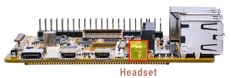
❶ Plug the Headset into the 3.5mm Audio jack.
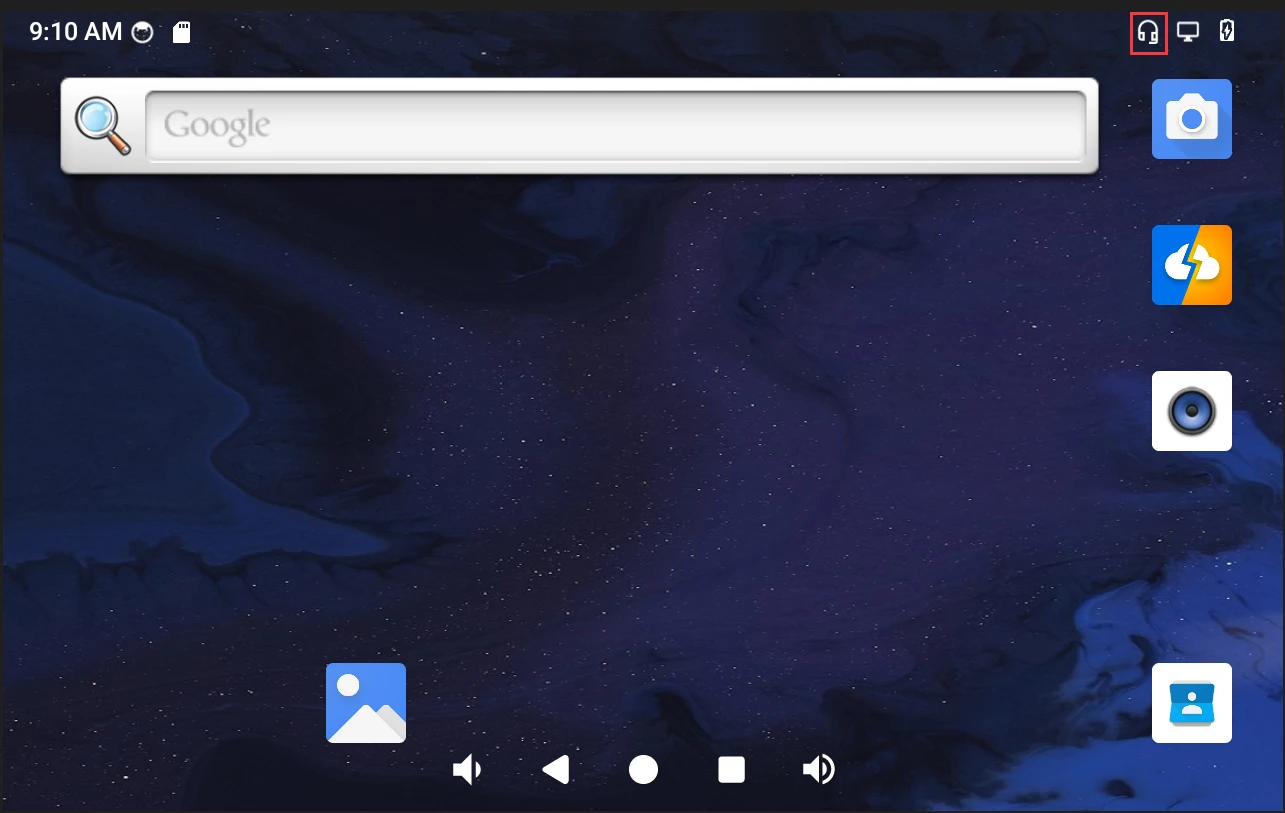
Headset insertion detected
❷ Open Sound Recorder
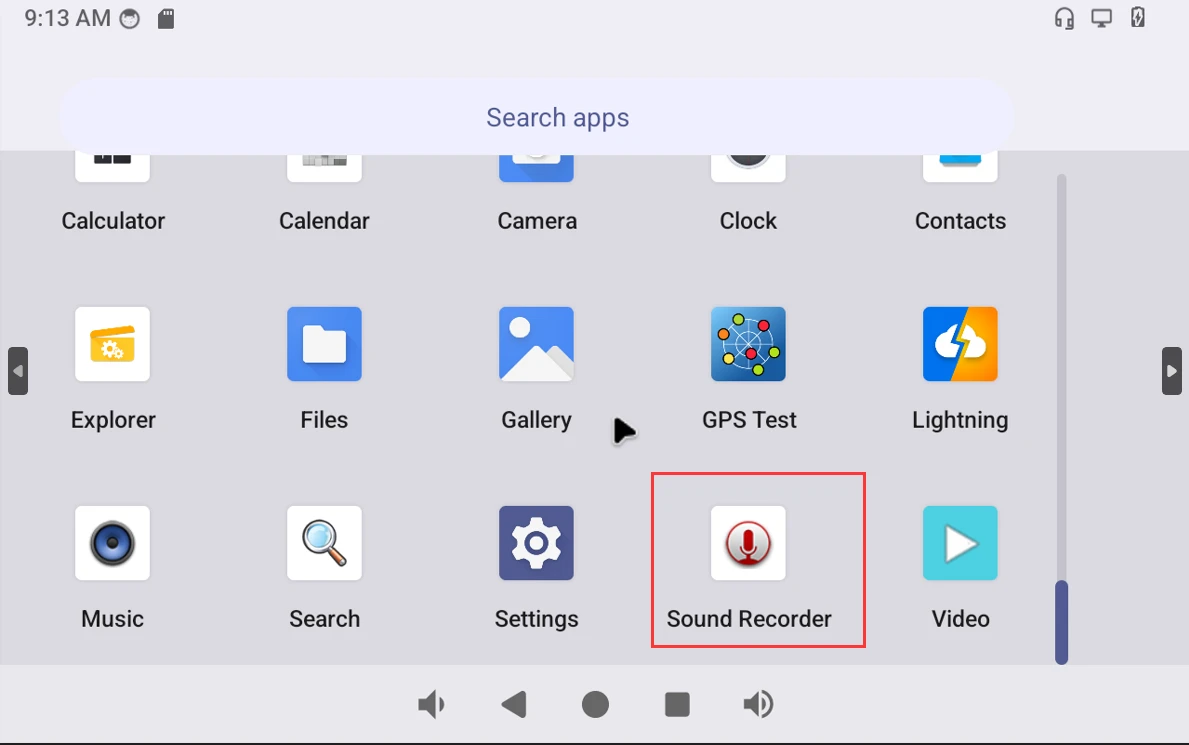
Record
❸ Click Start to start recording.
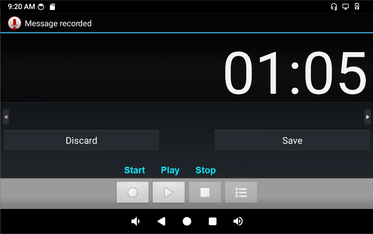
❹ After finish recording, click Stop -> play to test recorded file.
4.9 SD Card
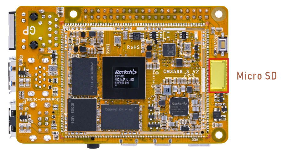
Idea3588S supports SD Hot-plug. Click Explorer to view the mounted SD card.
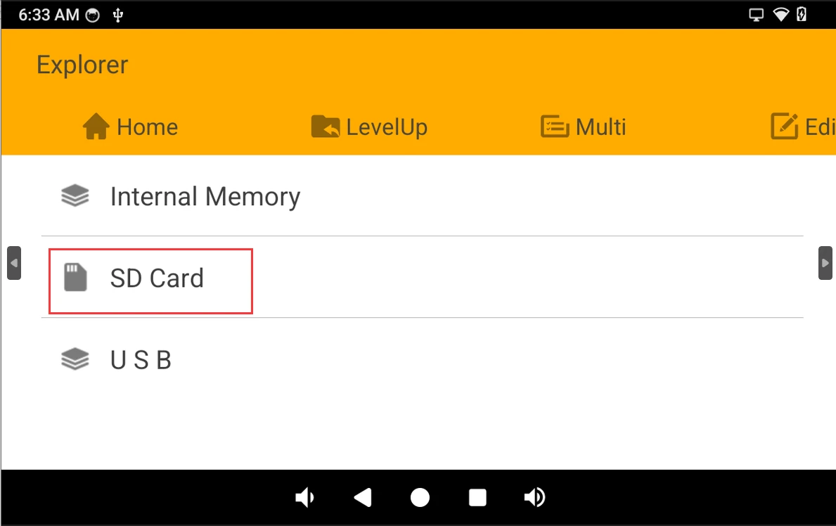
SD card
4.10 RTC
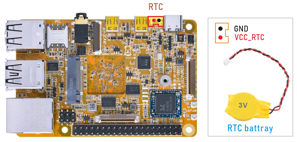
❶ Insert a 3V battery before test. It keeps the time running when the main power is off.
❷ Set date and time manually.
1date "2024-11-11 17:59:30"              //set system date
2hwclock -w                              //set the hardware clock to current system time
3hwclock                                 //display date and time
console:/ # date "2024-11-11 17:59:30"
Mon Nov 11 17:59:30 EST 2024
console:/ # hwclock -w
console:/ # hwclock
2024-11-11 22:59:38+0000
console:/ # hwclock
2024-11-11 22:59:54+0000
console:/ # hwclock
2024-11-11 23:00:05+0000
console:/ # hwclock
2024-11-11 23:00:26+0000
❸ Power off. Wait for a moment, power on again, and then execute the command hwclock, you will find that the time is saved.
console:/ # hwclock
2024-11-11 23:21:45+0000
console:/ # hwclock
2024-11-11 23:21:53+0000
console:/ # hwclock
2024-11-11 23:22:00+0000
console:/ # hwclock
2024-11-11 23:22:10+0000
If connected to the internet, the time will automatically synchronize with the network time.
4.11 Camera
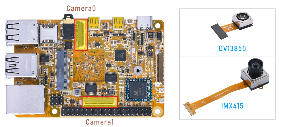
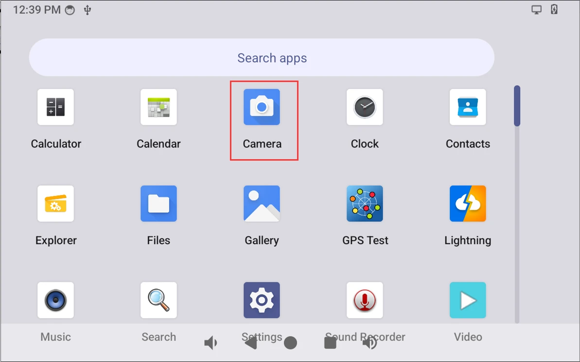
Compact3588s Camera0 and camera1 share the signal I2C3, Boardcon Android firmware default camera1 is enabled. Connect the module (IMX415) to the board before power on, then click the camera icon to test.
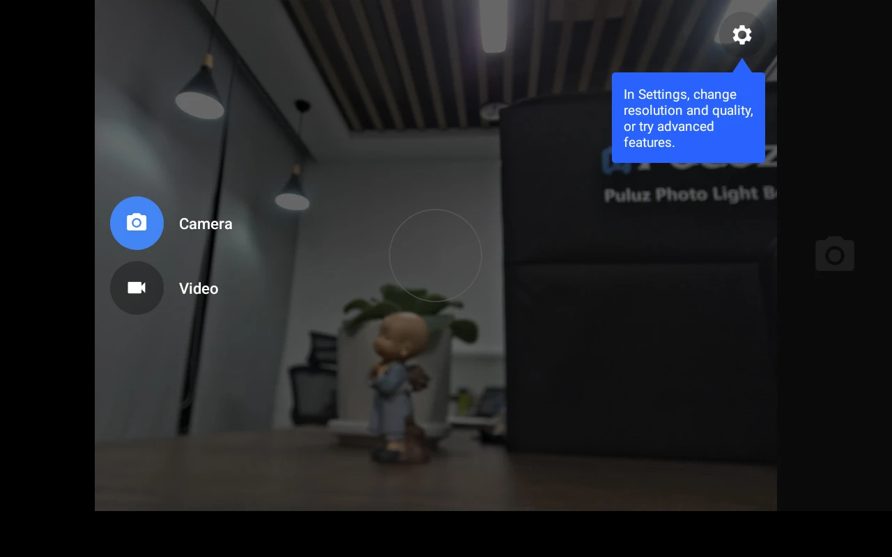
Camera preview
4.12 SPI
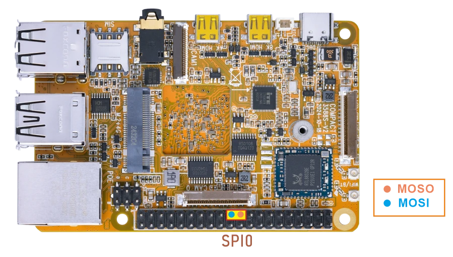
❶ Connect MOSI and MISO of SPI.
❷ SPI loopback test.
1spidev_test
console:/ # spidev_test
spi mode: 0
bits per word: 8
max speed: 10000000 Hz (10000 KHz)

FF FF FF FF FF FF
40 00 00 00 00 95
FF FF FF FF FF FF
FF FF FF FF FF FF
FF FF FF FF FF FF
DE AD BE EF BA AD
F0 0D
4.13 GPIO
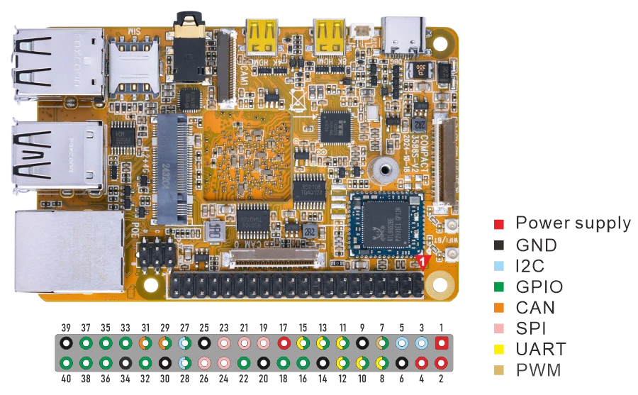
pin |
GPIO |
Device number |
pin |
GPIO |
Device number |
|---|---|---|---|---|---|
3 |
I2C3_SDA_M0_3V3 |
48 |
12 |
GPIO4_B5_d |
141 |
5 |
I2C3_SCL_M0_3V3 |
49 |
16 |
GPIO1_A2_d |
34 |
7 |
GPIO3_D5_d |
125 |
18 |
GPIO1_A3_d |
35 |
11 |
GPIO4_A6_d |
134 |
22 |
GPIO1_D0_d |
56 |
15 |
GPIO4_A3_d |
131 |
28 |
GPIO3_D2_d |
122 |
27 |
GPIO3_D3_d |
123 |
32 |
GPIO3_C6_u |
118 |
29 |
GPIO3_C4_u |
116 |
36 |
GPIO3_B7_d |
111 |
31 |
GPIO3_C5_u |
117 |
38 |
GPIO1_C2_d |
50 |
33 |
GPIO1_C6_d |
54 |
37 |
GPIO1_B0_u |
40 |
35 |
GPIO1_D5_d |
61 |
40 |
GPIO4_A7_d |
135 |
Test GPIO4_B5 for example.
1echo 141 > /sys/class/gpio/export
2echo "out" > /sys/class/gpio/gpio141/direction
3echo 1 > /sys/class/gpio/gpio141/value
4echo 0 > /sys/class/gpio/gpio141/value
5echo 141> /sys/class/gpio/unexport
The tests for other GPIOs are similar to those for GPIO4_B5.