4. Android Application
4.1 Serial Terminal
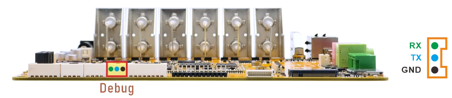
Connect the board and PC with USB Serial cable, then power on, the terminal will output boot information. The default baudrate is 1500000.
1su //switch to root mode
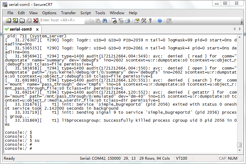
Serial Terminal
4.2 Display
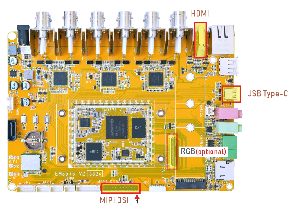
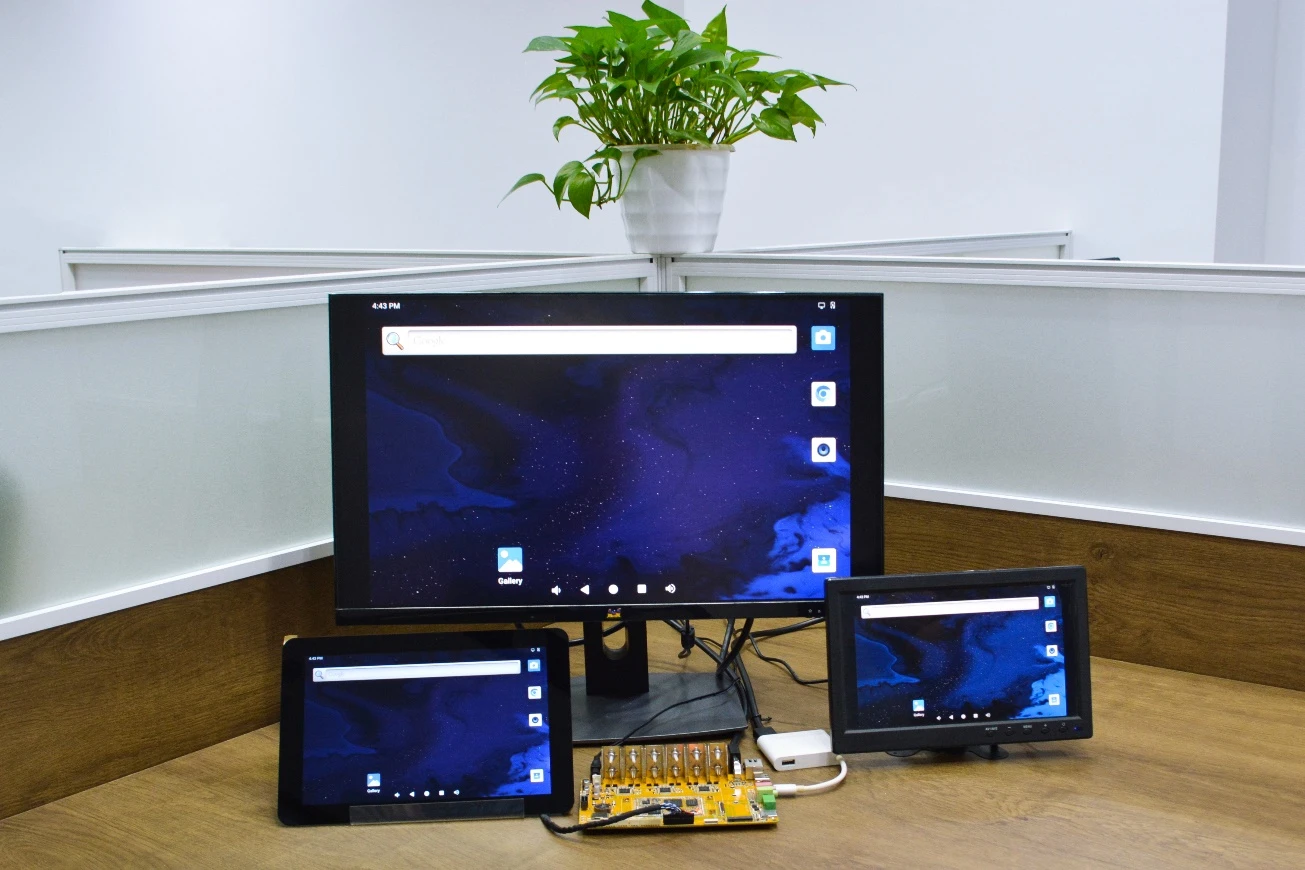
EM3576 supports MIPI LCD, HDMI and Type-C(DP Alt Mode) display synchronization.
The RGB signal is multiplexed with several interfaces. If RGB is required, please modify the hardware and kernel.
4.3 USB Type-C
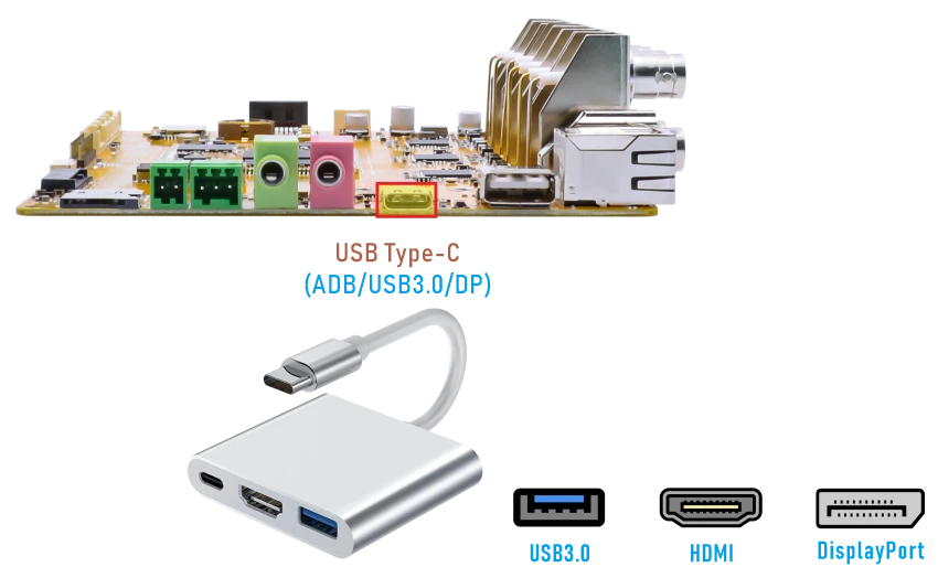
Features supported by the Type-C interface:
Reversible Design: Allows insertion in either orientation for user convenience.
Data Transmission Roles: Supports flexible designation of host and device roles.
Multiple Protocol Support: Compatible with USB 3.0 and DisplayPort, enabling high-speed data transmission.
4.3.1 ADB
❶ Connect the board and PC host with Type-C cable.
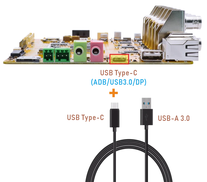
❷ Install ADB driver on Windows system.
❸ Press Windows + R to open the Run program. Type cmd and press Enter
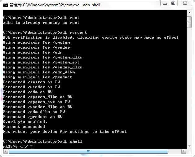
❹ Execute the follow commands to enable ADB.
1adb root
2adb remount
3adb shell
4.3.2 Type-C to USB
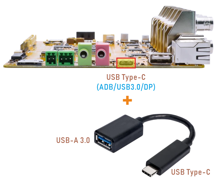
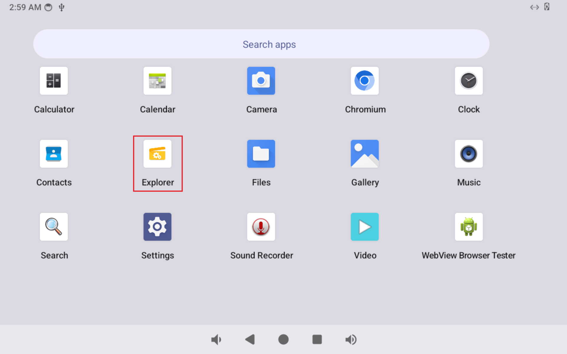
EM3576 supports Type-C to USB. The USB device can be used directly without install any driver. After inserting the U-disk, click Explorer icon to view the mounted device.
4.3.3 DP Alt Mode
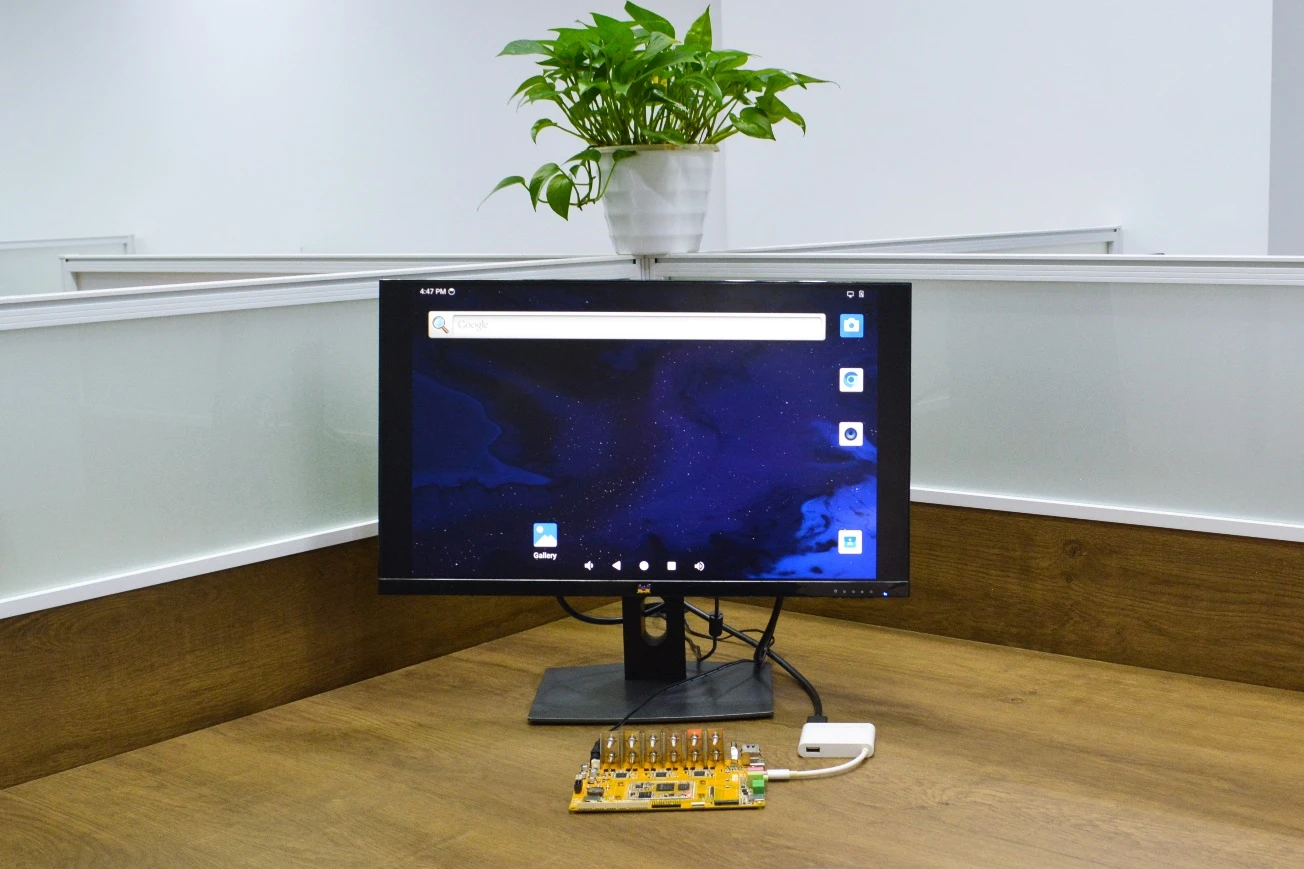
DisplayPort Alternate Mode (DP Alt Mode) is a technology that facilitates the transmission of DisplayPort video signals through a USB Type-C interface. It enables devices to output video and audio via a USB-C connection without requiring a dedicated DisplayPort connector. This allows users to connect a display using a single USB-C port while transmitting video, audio, and additional data.
Boardcon has conducted the testing at Type-C to HDMI/DP (3840 x 2160 @ 60fps).
Type-C to HDMI
4.4 USB Host
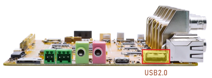
The USB2.0 Host can connect peripherals such as mouse, keyboards, and flash drives.
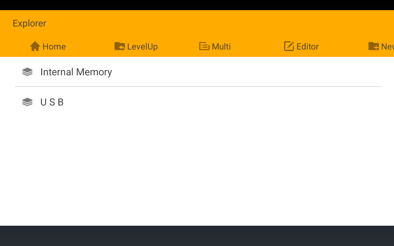
After inserting the U-disk, click Explorer icon to view the mounted device.
4.5 Ethernet
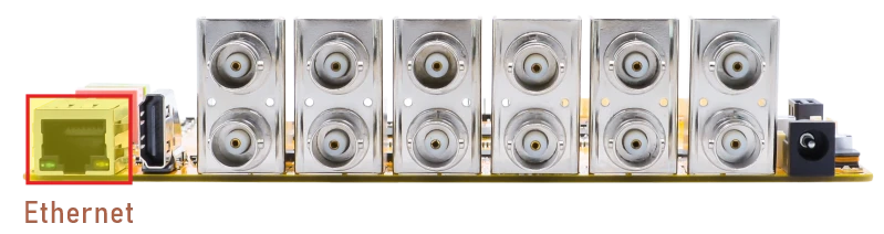
Connect the board and router with an Ethernet cable. According to the log, it can be seen that the Gigabit Ethernet recognition is successful.
console:/ #
[  110.719413][   T87] rk_gmac-dwmac 2a230000.ethernet eth0: Link is Up - 1Gbps/Full - flow control rx/tx
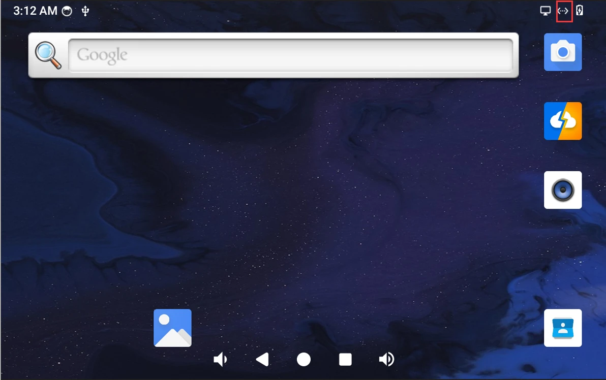
Network connected
Open browser Chromium or ping URL/IP to test Network.
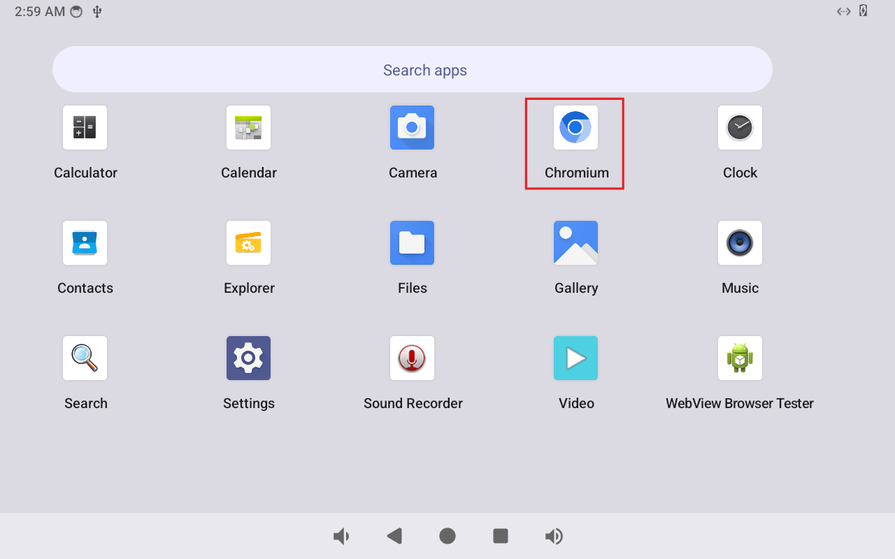
browser
1ifconfig
2ping -I eth0 www.armdesigner.com
console:/ # ifconfig
lo        Link encap:Local Loopback
          inet addr:127.0.0.1  Mask:255.0.0.0
          inet6 addr: ::1/128 Scope: Host
          UP LOOPBACK RUNNING  MTU:65536  Metric:1
          RX packets:2 errors:0 dropped:0 overruns:0 frame:0
          TX packets:2 errors:0 dropped:0 overruns:0 carrier:0
          collisions:0 txqueuelen:1000
          RX bytes:106 TX bytes:106

dummy0    Link encap:Ethernet  HWaddr 5e:b8:c7:bc:14:10
          inet6 addr: fe80::5cb8:c7ff:febc:1410/64 Scope: Link
          UP BROADCAST RUNNING NOARP  MTU:1500  Metric:1
          RX packets:0 errors:0 dropped:0 overruns:0 frame:0
          TX packets:6 errors:0 dropped:0 overruns:0 carrier:0
          collisions:0 txqueuelen:1000
          RX bytes:0 TX bytes:420

eth0      Link encap:Ethernet  HWaddr 6e:95:7b:2b:8a:ff  Driver rk_gmac-dwmac
          inet addr:192.168.0.140  Bcast:192.168.0.255  Mask:255.255.255.0
          inet6 addr: fe80::a9d5:e5cd:cbfc:f97b/64 Scope: Link
          UP BROADCAST RUNNING MULTICAST  MTU:1500  Metric:1
          RX packets:575 errors:0 dropped:0 overruns:0 frame:0
          TX packets:321 errors:0 dropped:0 overruns:0 carrier:0
          collisions:0 txqueuelen:1000
          RX bytes:117763 TX bytes:34799
          Interrupt:63

 console:/ # ping -I eth0 www.armdesigner.com
 PING www.armdesigner.com (67.222.54.196) from 192.168.0.140 eth0: 56(84) bytes of data.
 64 bytes from 67-222-54-196.unifiedlayer.com (67.222.54.196): icmp_seq=1 ttl=48 time=188 ms
 64 bytes from 67-222-54-196.unifiedlayer.com (67.222.54.196): icmp_seq=2 ttl=48 time=191 ms
 64 bytes from 67-222-54-196.unifiedlayer.com (67.222.54.196): icmp_seq=3 ttl=48 time=187 ms
 64 bytes from 67-222-54-196.unifiedlayer.com (67.222.54.196): icmp_seq=4 ttl=48 time=188 ms
 64 bytes from 67-222-54-196.unifiedlayer.com (67.222.54.196): icmp_seq=5 ttl=48 time=190 ms
 ^X64 bytes from 67-222-54-196.unifiedlayer.com (67.222.54.196): icmp_seq=6 ttl=48 time=187 ms
 64 bytes from 67-222-54-196.unifiedlayer.com (67.222.54.196): icmp_seq=7 ttl=48 time=190 ms
 ^C
 --- www.armdesigner.com ping statistics ---
 7 packets transmitted, 7 received, 0% packet loss, time 6002ms
 rtt min/avg/max/mdev = 187.253/189.211/191.123/1.504 ms
4.6 SATA
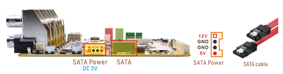
Important
SATA cannot be used with USB2.0 Host simultaneously. Boardcon Android firmware default SATA is unavailable. To enable SATA, please reflash the image boot_sata.img
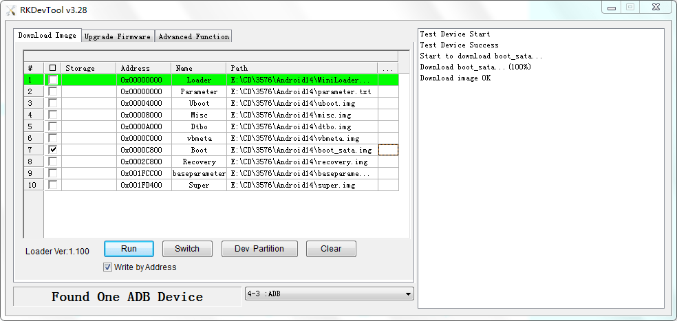
❶ Connect SATA and SATA power(5V).
❷ Power on.
❸ Format SATA to ext4. If the device is in ext4 format, skip this step.
1mke2fs -t ext4 /dev/block/sda1
Warning
This operation will permanently erase all existing data on the selected partition. Before running the command below, double‑check that the device path is correct.
❹ Click Explorer icon to view the mounted SATA.
4.7 SD Card
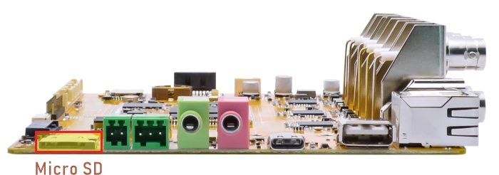
EM3576 supports SD Hot-plug.
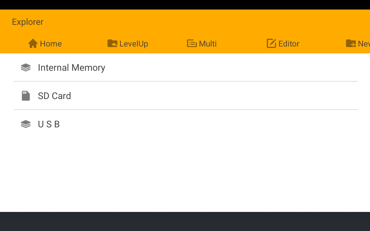
After insert the microSD card into the slot, click Explorer to view the mounted SD card.
4.8 M.2 SSD
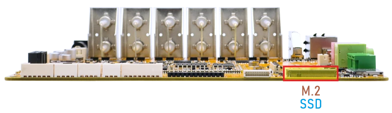
EM3576 only supports SSD in ext4 format.
❶ Connect SSD to the M.2 slot.
❷ Power on.
❸ Format SSD to ext4. If the device is in ext4 format, skip this step.
1mke2fs -t ext4 /dev/block/nvme0n1
Warning
This operation will permanently erase all existing data on the selected partition. Before running the command below, double‑check that the device path is correct.
❹ Execute the command to manually mount the SSD.
The Boardcon Android firmware currently does not support automatic mounting of SSD.
1mkdir /data/ssd
2mount -t ext4 /dev/block/nvme0n1 /data/ssd
3ls /data/ssd
4.9 WiFi & Bluetooth
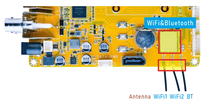
4.9.1 WiFi
❶ Connect the WiFi antenna.
❷ Click Settings -> Network & internet -> Internet -> Wi-Fi, turn on Wi-Fi.
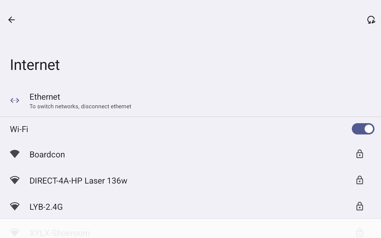
Turn on Wi-Fi
❸ Select the SSID from the list of available networks and enter the password.
After connected, open the browser or ping URL/IP at terminal to test Network.
1ifconfig
2ping -I wlan0 www.armdesigner.com
console:/ # ifconfig
lo        Link encap:Local Loopback
          inet addr:127.0.0.1  Mask:255.0.0.0
          inet6 addr: ::1/128 Scope: Host
          UP LOOPBACK RUNNING  MTU:65536  Metric:1
          RX packets:2 errors:0 dropped:0 overruns:0 frame:0
          TX packets:2 errors:0 dropped:0 overruns:0 carrier:0
          collisions:0 txqueuelen:1000
          RX bytes:106 TX bytes:106

dummy0    Link encap:Ethernet  HWaddr 4a:b1:e3:60:12:91
          inet6 addr: fe80::48b1:e3ff:fe60:1291/64 Scope: Link
          UP BROADCAST RUNNING NOARP  MTU:1500  Metric:1
          RX packets:0 errors:0 dropped:0 overruns:0 frame:0
          TX packets:5 errors:0 dropped:0 overruns:0 carrier:0
          collisions:0 txqueuelen:1000
          RX bytes:0 TX bytes:350

eth0      Link encap:Ethernet  HWaddr 6e:95:7b:2b:8a:ff  Driver rk_gmac-dwmac
          UP BROADCAST MULTICAST  MTU:1500  Metric:1
          RX packets:0 errors:0 dropped:0 overruns:0 frame:0
          TX packets:0 errors:0 dropped:0 overruns:0 carrier:0
          collisions:0 txqueuelen:1000
          RX bytes:0 TX bytes:0
          Interrupt:63

wlan0     Link encap:Ethernet  HWaddr 38:7a:cc:2a:09:33  Driver rtl88x2cs
          inet addr:192.168.0.144  Bcast:192.168.0.255  Mask:255.255.255.0
          inet6 addr: fe80::4b77:5637:e9c3:7d69/64 Scope: Link
          UP BROADCAST RUNNING MULTICAST  MTU:1500  Metric:1
          RX packets:322 errors:0 dropped:1 overruns:0 frame:0
          TX packets:111 errors:0 dropped:0 overruns:0 carrier:0
          collisions:0 txqueuelen:1000
          RX bytes:61593 TX bytes:15157

console:/ # ping -I wlan0 www.armdesigner.com
PING www.armdesigner.com (67.222.54.196) from 192.168.0.144 wlan0: 56(84) bytes of data.
64 bytes from 67-222-54-196.unifiedlayer.com (67.222.54.196): icmp_seq=1 ttl=48 time=196 ms
64 bytes from 67-222-54-196.unifiedlayer.com (67.222.54.196): icmp_seq=2 ttl=48 time=189 ms
64 bytes from 67-222-54-196.unifiedlayer.com (67.222.54.196): icmp_seq=3 ttl=48 time=189 ms
64 bytes from 67-222-54-196.unifiedlayer.com (67.222.54.196): icmp_seq=4 ttl=48 time=225 ms
64 bytes from 67-222-54-196.unifiedlayer.com (67.222.54.196): icmp_seq=5 ttl=48 time=248 ms
^C
--- www.armdesigner.com ping statistics ---
5 packets transmitted, 5 received, 0% packet loss, time 4464ms
rtt min/avg/max/mdev = 189.233/209.876/248.002/23.195 ms
4.9.2 Bluetooth
Click Settings -> Connected devices -> Pair new device
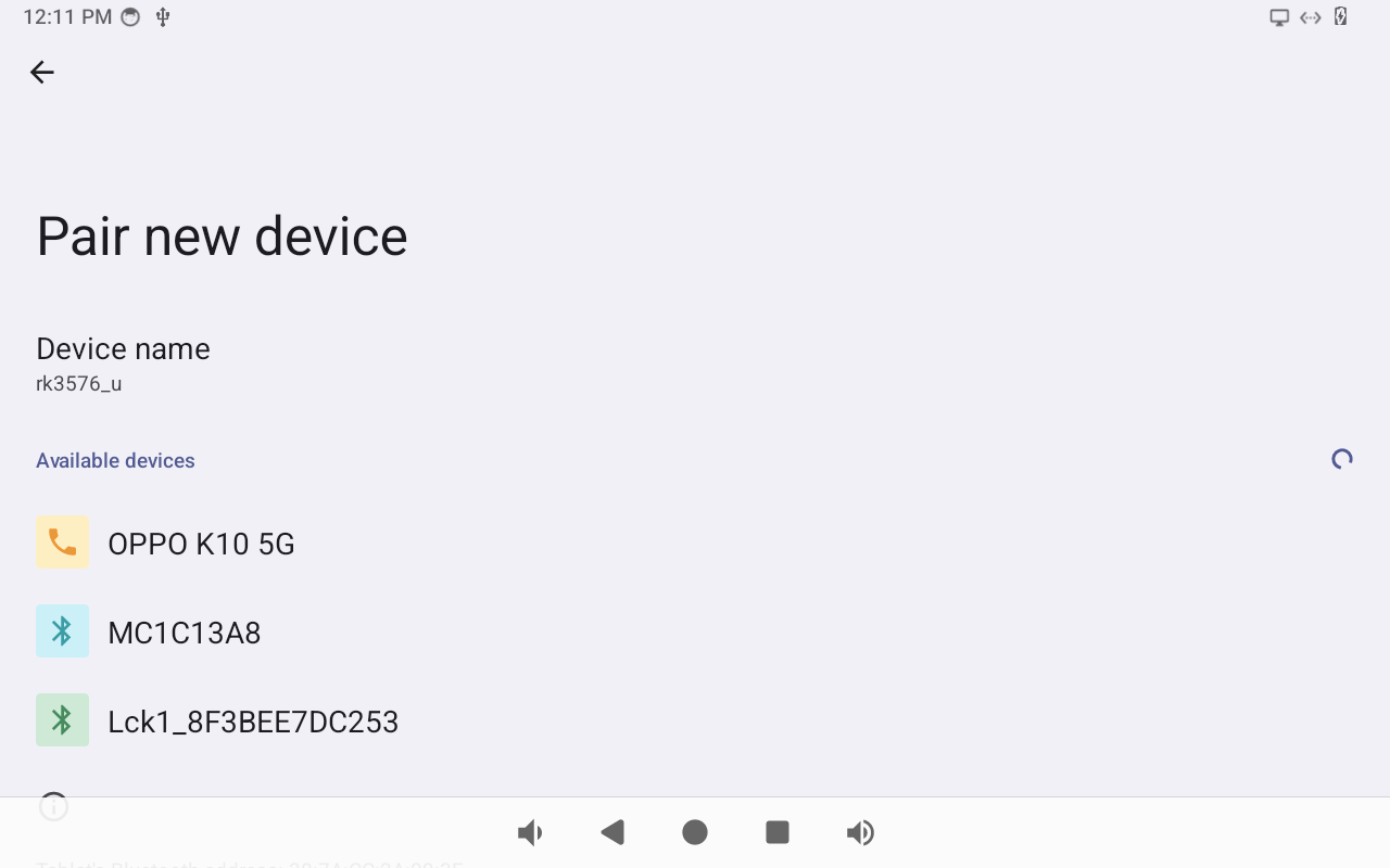
Select the available device in the list to pair. After pairing, devices can connect with each other automatically.
4.10 Audio I/O
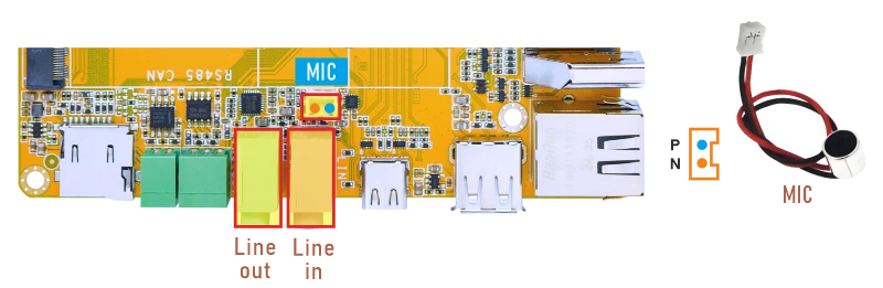
4.10.1 Audio in
4.10.1.1 Line in
❶ Plug the Microphone into the 3.5mm Audio jack(Line in).
❷ Open Sound Recorder
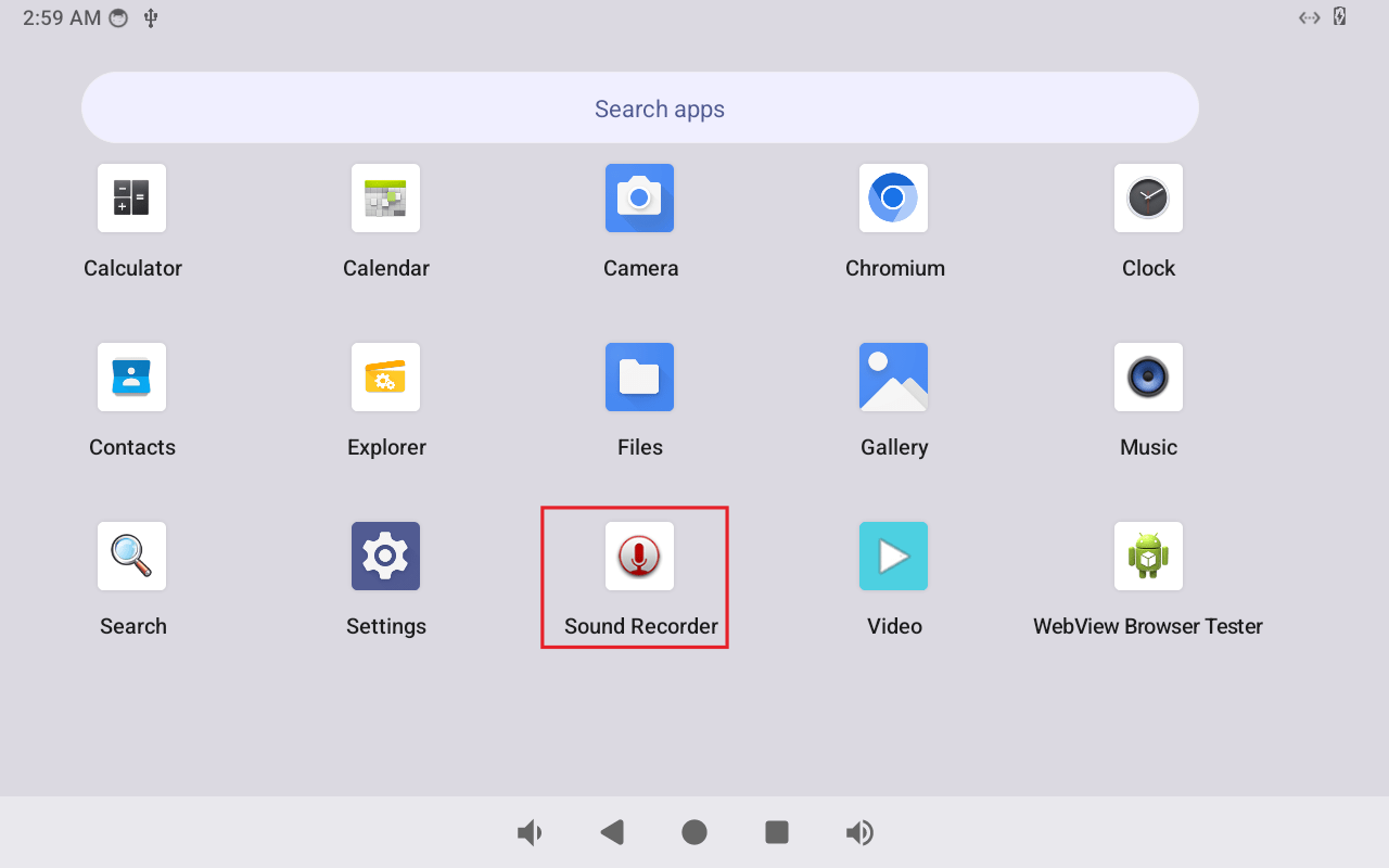
Record
❸ Click Start icon.
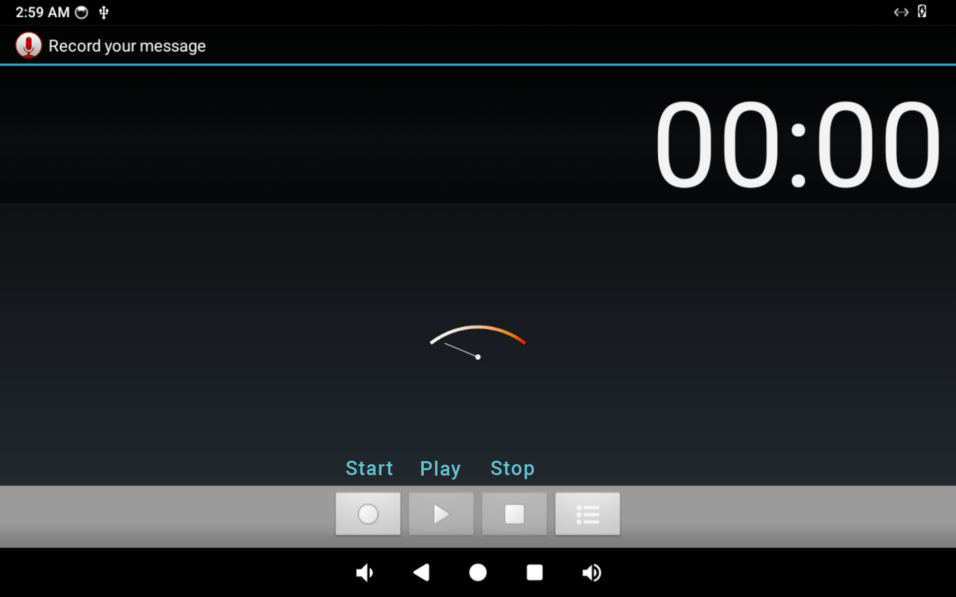
Execute commands to open record line.
1tinymix 67 1
2tinymix 68 1
3tinymix
console:/ # tinymix 67 1
console:/ # tinymix 68 1
console:/ # tinymix
Mixer name: 'rockchip-es8388'
Number of controls: 79
ctl     type    num     name                                     value
61      BOOL    1       spk switch                               Off
62      BOOL    1       hp switch                                Off
63      BOOL    1       Headphone Switch                         On
64      BOOL    1       Speaker Switch                           On
65      BOOL    1       Main Mic Switch                          On
66      BOOL    1       Headset Mic Switch                       On
67      ENUM    1       Left PGA Mux                             Line 2L
68      ENUM    1       Right PGA Mux                            Line 2R
69      ENUM    1       Differential Mux                         Line 2
❹ After finish recording, click Stop -> play to test recorded file.
4.10.1.2 MIC
❶ Connect a MIC to the connector (2pin/2.0mm pitch).
❷ Open Sound Recorder
❸ Click Start icon.
Execute commands to switch MIC channel to record.
1tinymix 69 0
2tinymix
console:/ # tinymix 69 0
console:/ # tinymix
Mixer name: 'rockchip-es8388'
Number of controls: 79
ctl     type    num     name                                     value
54      ENUM    1       Capture Polarity                         Normal
55      INT     2       PCM Volume                               192 192
56      INT     1       Left Mixer Left Bypass Volume            0
57      INT     1       Right Mixer Right Bypass Volume          0
58      INT     2       Output 1 Playback Volume                 0 0
59      INT     2       Output 2 Playback Volume                 0 0
60      ENUM    1       ADC Data Select                          Left Left
61      BOOL    1       spk switch                               Off
62      BOOL    1       hp switch                                Off
63      BOOL    1       Headphone Switch                         On
64      BOOL    1       Speaker Switch                           On
65      BOOL    1       Main Mic Switch                          On
66      BOOL    1       Headset Mic Switch                       On
67      ENUM    1       Left PGA Mux                             Line 2L
68      ENUM    1       Right PGA Mux                            Line 2R
69      ENUM    1       Differential Mux                         Line 1
70      ENUM    1       Mono Mux                                 Stereo
71      ENUM    1       Left Line Mux                            Line 1L
72      ENUM    1       Right Line Mux                           Line 1R
73      BOOL    1       Left Mixer Left Playback Switch          Off
74      BOOL    1       Left Mixer Left Bypass Switch            Off
75      BOOL    1       Right Mixer Right Playback Switch        Off
76      BOOL    1       Right Mixer Right Bypass Switch          Off
77      BOOL    1       OUT1 Switch                              Off
78      BOOL    1       OUT2 Switch                              Off
❹ After finish recording, click Stop -> Play to test recorded file.
4.10.2 Audio out
4.10.2.1 Test by APP
Audio output priority: HDMI > USB Type-C(DP AIT mode) > Line out.
❶ Plug the headphone into the 3.5mm Audio jack(Line out).
❷ Open Music
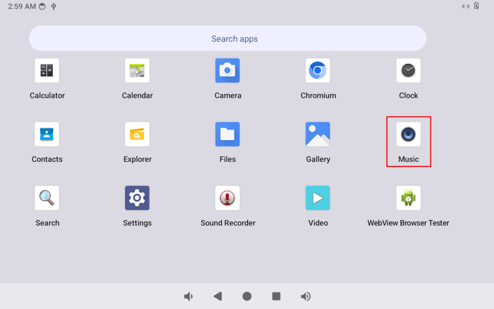
❸ Select an audio file to play.
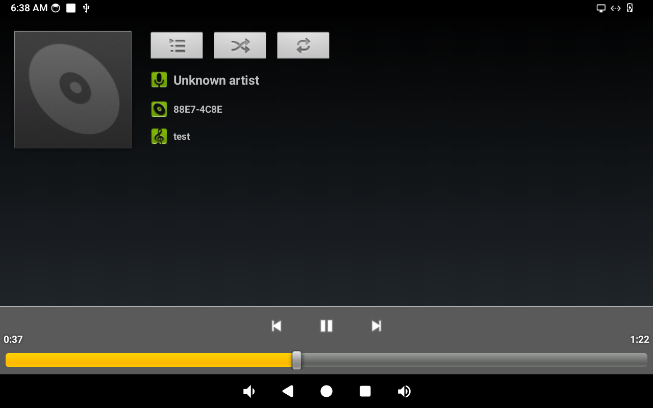
Play music
4.10.2.1 Test by Command
❶ Put the audio file the the sdcard or U-disk then execute the following command to view sound card.
1cat /proc/asound/cards
console:/ # cat /proc/asound/cards
 0 [rockchipes8388 ]: rockchip-es8388 - rockchip-es8388
                      rockchip-es8388
 1 [rockchipdp0    ]: rockchip-dp0 - rockchip-dp0
                      rockchip-dp0
 2 [rockchiphdmi   ]: rockchip-hdmi - rockchip-hdmi
                      rockchip-hdmi
❷ Enable playback switch.
1tinymix 73 1
2tinymix 75 1
❸ Play audio via Line out.
1tinyplay test.wav -D 0 -d 0 -p 1024 -n 3
# Audio via Line Out
tinyplay test.wav -D 0 -d 0 -p 1024 -n 3

# Audio via DP AIT mode
tinyplay test.wav -D 1 -d 0 -p 1024 -n 3

# Audio via HDMI TX
tinyplay test.wav -D 2 -d 0 -p 1024 -n 3
4.11 RTC
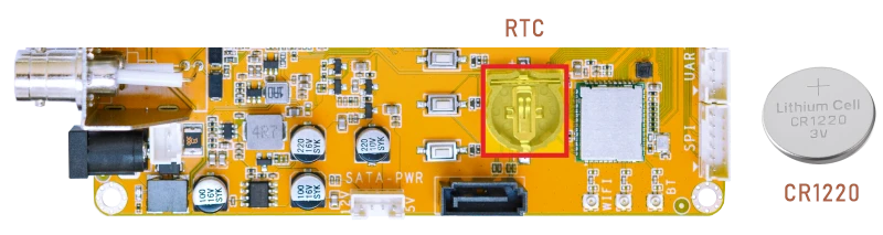
❶ Insert a CR1220 battery before test. It keeps the time running when the main power is off.
❷ Set date and time manually.
1date -s "2025-01-14 14:53:00"     //set system date
2hwclock -w                        //set the hardware clock to current system time
3hwclock                           //display date and time
console:/ # date -s "2025-01-14 14:53:00"
Tue Jan 14 14:53:00 GMT 2025
console:/ # hwclock -w
console:/ # hwclock
2025-01-14 14:53:07+0000
console:/ # hwclock
2025-01-14 14:53:08+0000
console:/ # hwclock
2025-01-14 14:53:10+0000
console:/ # hwclock
2025-01-14 14:53:11+0000
❸ Power off the board. Wait a while, then reapply power. If the RTC is functioning correctly, the clock should maintain its time and keep running while the board is powered off.
console:/ # hwclock
2025-01-14 14:54:24+0000
console:/ # hwclock
2025-01-14 14:54:26+0000
console:/ # hwclock
2025-01-14 14:54:26+0000
console:/ # hwclock
2025-01-14 14:54:27+0000
console:/ # hwclock
2025-01-14 14:54:28+0000
If connected to the internet, the time will automatically synchronize with the network time.
4.12 RS485
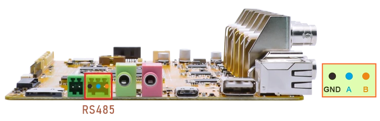
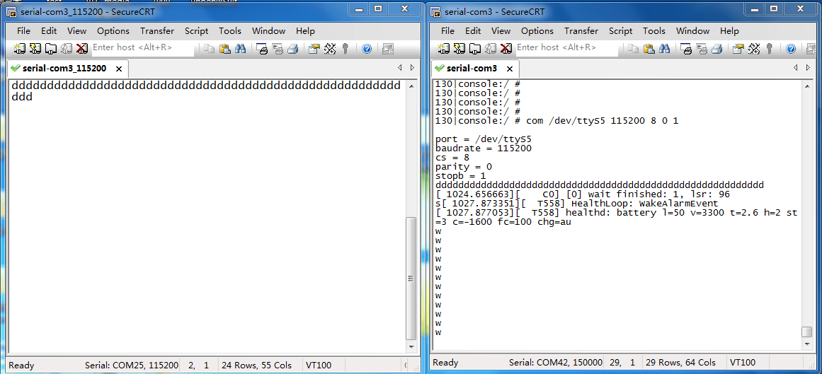
❶ Connect PC and board with USB-to-RS485 adapter.
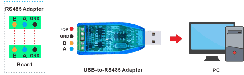
RS485 connection
❷ Open the Serial Terminal and set baud rate for RS485 adapter and EM3576 respectively.
Baud rate: RS485 adapter - 115200; EM3576 - 1500000
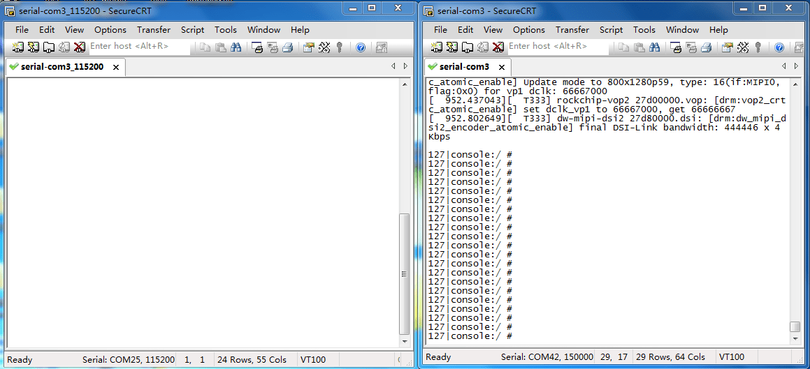
❸ Execute command in the terminal of the board.
1com /dev/ttyS5 115200 8 0 1
❹ Input character to test RS485 communication.
4.13 CAN
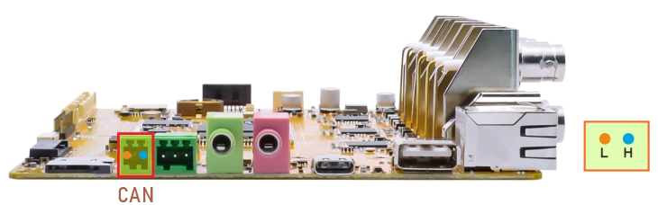
❶ Connect PC and board with USB-to-CAN adapter.
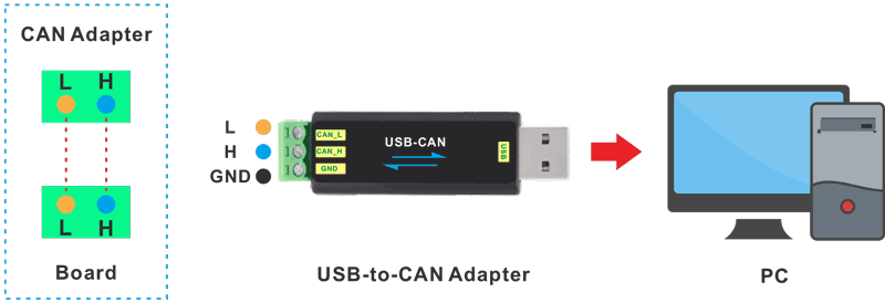
CAN connection
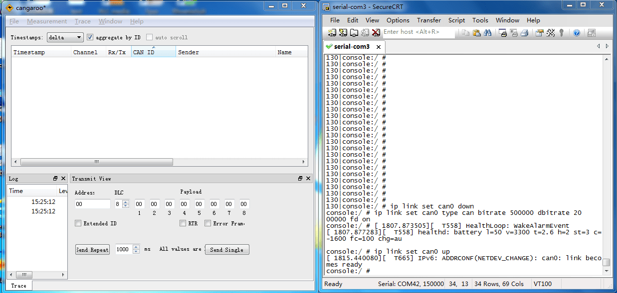
❷ Open the CAN application and set the baudrate to 500000 on PC.
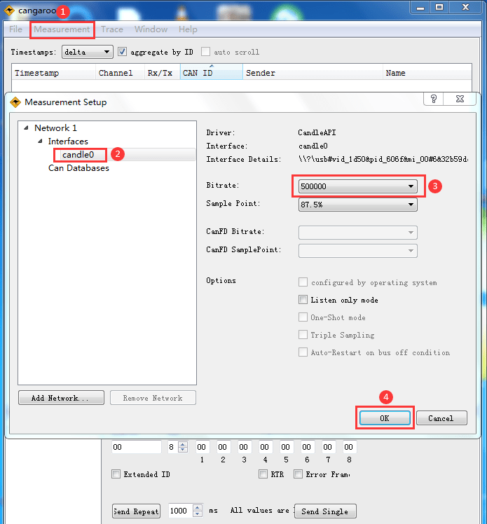
CAN baudrate
❸ Execute commands on Serial Terminal to configure CAN.
1ip link set can0 down
2ip link set can0 type can bitrate 500000 dbitrate 2000000 fd on
3ip link set can0 up
❹ Configure CAN as receiver.
1candump can0

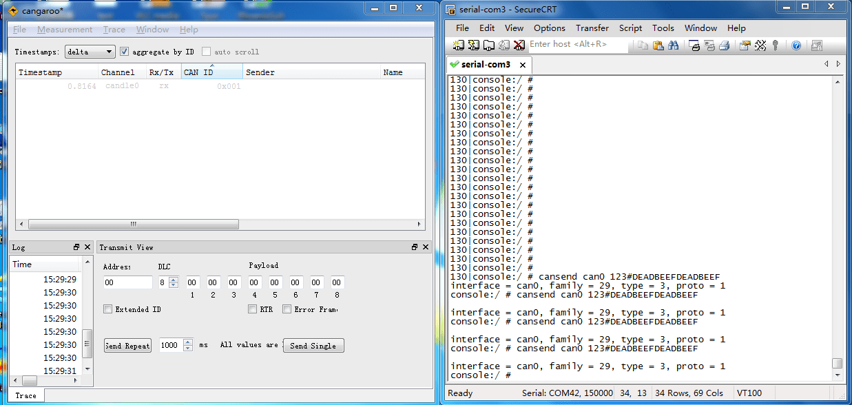
❺ Configure CAN as Transmitter.
1cansend can0 123#DEADBEEFDEADBEEF
4.14 UART
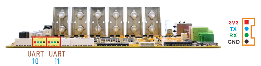
The UART loopback test is for reference only.
❶ Connect RX and TX of UART.
❷ Execute command and input character to test.
1com /dev/ttyS10 115200 8 0 1 //test UART10
console:/ # com /dev/ttyS10 115200 8 0 1
port = /dev/ttyS10
baudrate = 115200
cs = 8
parity = 0
stopb = 1
1234567890
abcdefghij
❸ Press Ctrl + C to exit UART10 testing.
❹ Execute command to test UART11.
1com /dev/ttyS11 115200 8 0 1
4.15 SPI
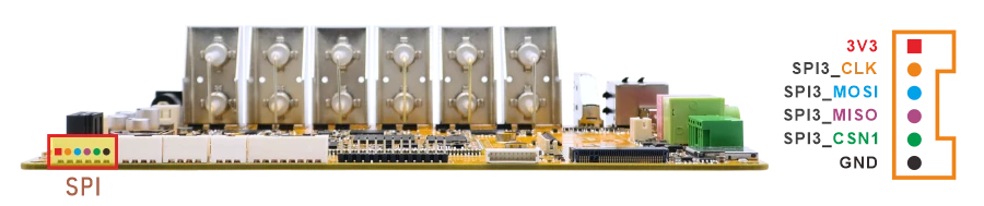
❶ Connect SPI3_MISO and SPI3_MOSI of SPI.
❷ Execute the test script spidev_test
1spidev_test
console:/ # spidev_test
spi mode: 0
bits per word: 8
max speed: 500000 Hz (500 KHz)

FF FF FF FF FF FF
40 00 00 00 00 95
FF FF FF FF FF FF
FF FF FF FF FF FF
FF FF FF FF FF FF
DE AD BE EF BA AD
F0 0D
4.16 Camera
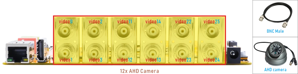
❶ Connect AHD camera to the development board.
❷ Test single preview with video0
1v4l2-ctl --verbose -d /dev/video0 --set-fmt-video=width=1920,height=1080,pixelformat='NV12' --stream-mmap=4 --set-selection=target=crop,flags=0,top=0,left=0,width=1920,height=1080 --stream-to=./out0_0.yuv
console:/mnt/media_rw/8CF4-026D # v4l2-ctl --verbose -d /dev/video0 --set-fmt-video=width=1920,height=1080,pixelformat='NV12' --stream-mmap=4 --set-selection=target=crop,flags=0,top=0,left=0,width=1920,height=1080 --stream-to=./out0_0.yuv
VIDIOC_QUERYCAP: ok
[  587.907508][ T2194] rkcif-mipi-lvds: static crop, S_SELECTION(1920x1080@0:0) target: 0
VIDIOC_G_FMT: ok
VIDIOC_S_FMT: ok
Format Video Capture Multiplanar:
        Width/Height      : 1920/1080
        Pixel Format      : 'NV12'
        Field             : None
        Number of planes  : 1
        Flags             :
        Colorspace        : Default
        Transfer Function : Default
        YCbCr Encoding    : Default
        Quantization      : Default
        Plane 0           :
           Bytes per Line : 1920
           Size Image     : 3110400
VIDIOC_G_SELECTION: ok
VIDIOC_S_SELECTION: ok
VIDIOC_REQBUFS: ok
VIDIOC_QUERYBUF: ok
VIDIOC_QUERYBUF: ok
VIDIOC_QBUF: ok
VIDIOC_QUERYBUF: ok
VIDIOC_QBUF: ok
VIDIOC_QUERYBUF: ok
VIDIOC_QBUF: ok
VIDIOC_QUERYBUF: ok
VIDIOC_QBUF: ok
[  587.917395][ T2194] rkcif-mipi-lvds: stream[0] start streaming
[  587.919464][ T2194] rkcif-mipi-lvds: Allocate dummy buffer, size: 0x003f5000
[  587.921716][ T2194] rockchip-mipi-csi2 mipi0-csi2: stream on, src_sd: 0000000040209343, sd_name:rockchip-csi2-dphy0
[  587.921818][ T2194] rockchip-mipi-csi2 mipi0-csi2: stream ON
[  587.921872][ T2194] rockchip-csi2-dphy0: dphy0, data_rate_mbps 594
[  587.922174][ T2194] rockchip-csi2-dphy csi2-dphy0: csi2_dphy_s_stream stream on:1, dphy0, ret 0
[  587.923563][ T2194] reso_dtect = 7
[  587.923581][ T2194] techpoint 7-0047: detect channel 0 is not supported, default 1080P_25
[  587.924373][ T2194] techpoint 7-0047: set channel 0 1080P_25
[  587.967839][ T2194] reso_dtect = 3
[  587.968000][ T2194] techpoint 7-0047: detect channel 1 1080P_25
[  587.969050][ T2194] techpoint 7-0047: set channel 1 1080P_25
[  588.015133][ T2194] reso_dtect = 7
[  588.015288][ T2194] techpoint 7-0047: detect channel 2 is not supported, default 1080P_25
[  588.016347][ T2194] techpoint 7-0047: set channel 2 1080P_25
[  588.062278][ T2194] reso_dtect = 7
[  588.062423][ T2194] techpoint 7-0047: detect channel 3 is not supported, default 1080P_25
[  588.063482][ T2194] techpoint 7-0047: set channel 3 1080P_25
[  588.122844][    C0] (0x27c80000)MIPI_CSI2 ERR1:0xff0 (fs/fe mis,vc: 0 1 2 3) (f_seq,vc: 0 1 2 3)
VIDIOC_STREAMON: ok
idx: 0 seq:      0 bytesused: 3110400 ts: 587.268879
idx: 1 seq:      1 bytesused: 3110400 ts: 587.308881 delta: 40.002 ms
idx: 2 seq:      2 bytesused: 3110400 ts: 587.348899 delta: 40.018 ms
The file out0_0.yuv will be saved in the current directory.
console:/mnt/media_rw/8CF4-026D # ls
1.png     Audiobooks         Pictures                     s.png
2.png     DCIM               Podcasts                     s1.png
3.png     Documents          Recordings                   s2.png
4.png     Download           Ringtones                    s3.png
4k.mp4    Go-home.mp3        System\ Volume\ Information  s4.png
4k60.mp4  Hejie-jingguo.mp3  black_list                   snapshot
5.png     LOST.DIR           log                          test.wav
6.png     Movies             out0_0.yuv                   video0
Alarms    Music              photo0                       video1
Android   Notifications      photo1                       white_list
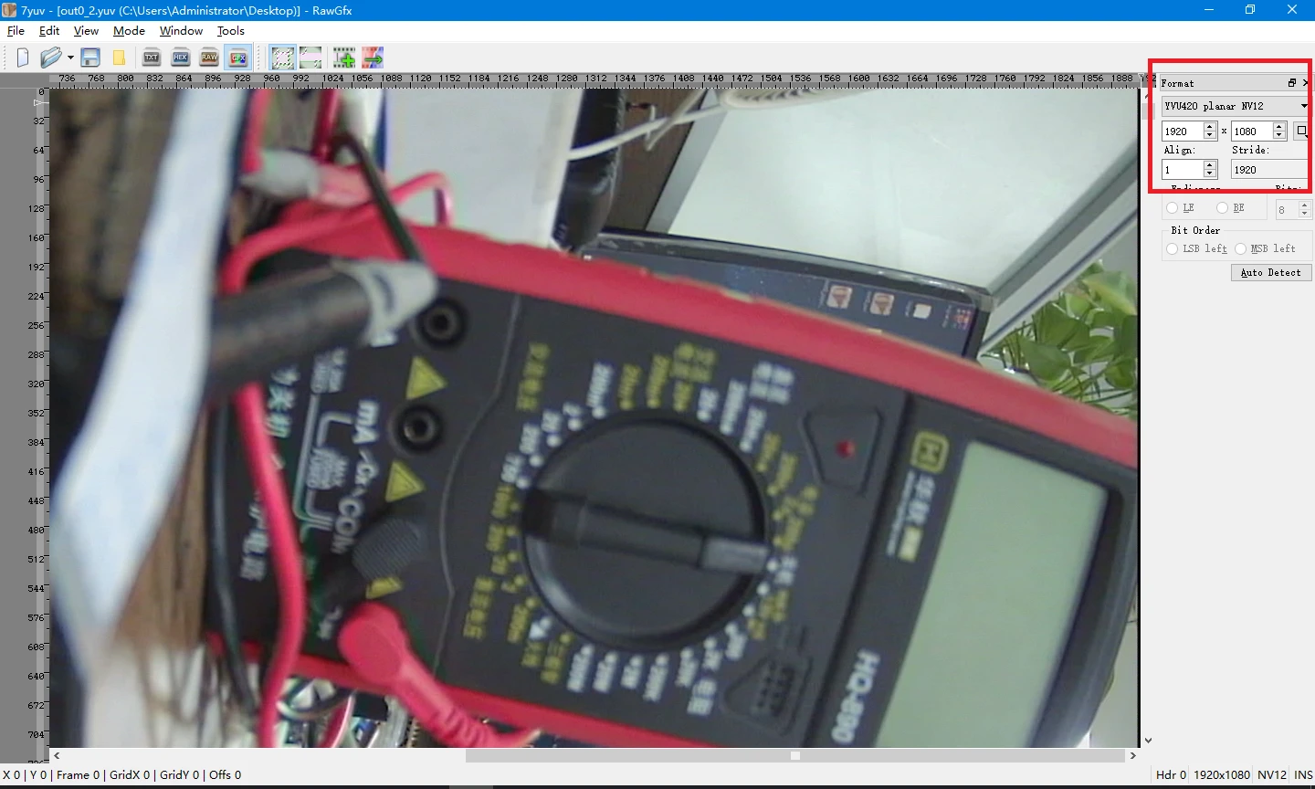
❸ Copy the file to PC and view via 7yuv tool.
4.17 Video Playback
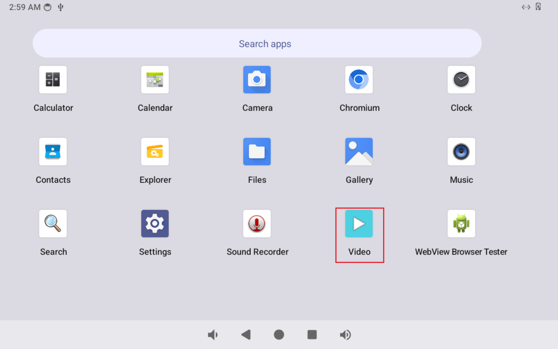
❶ Click Video icon.
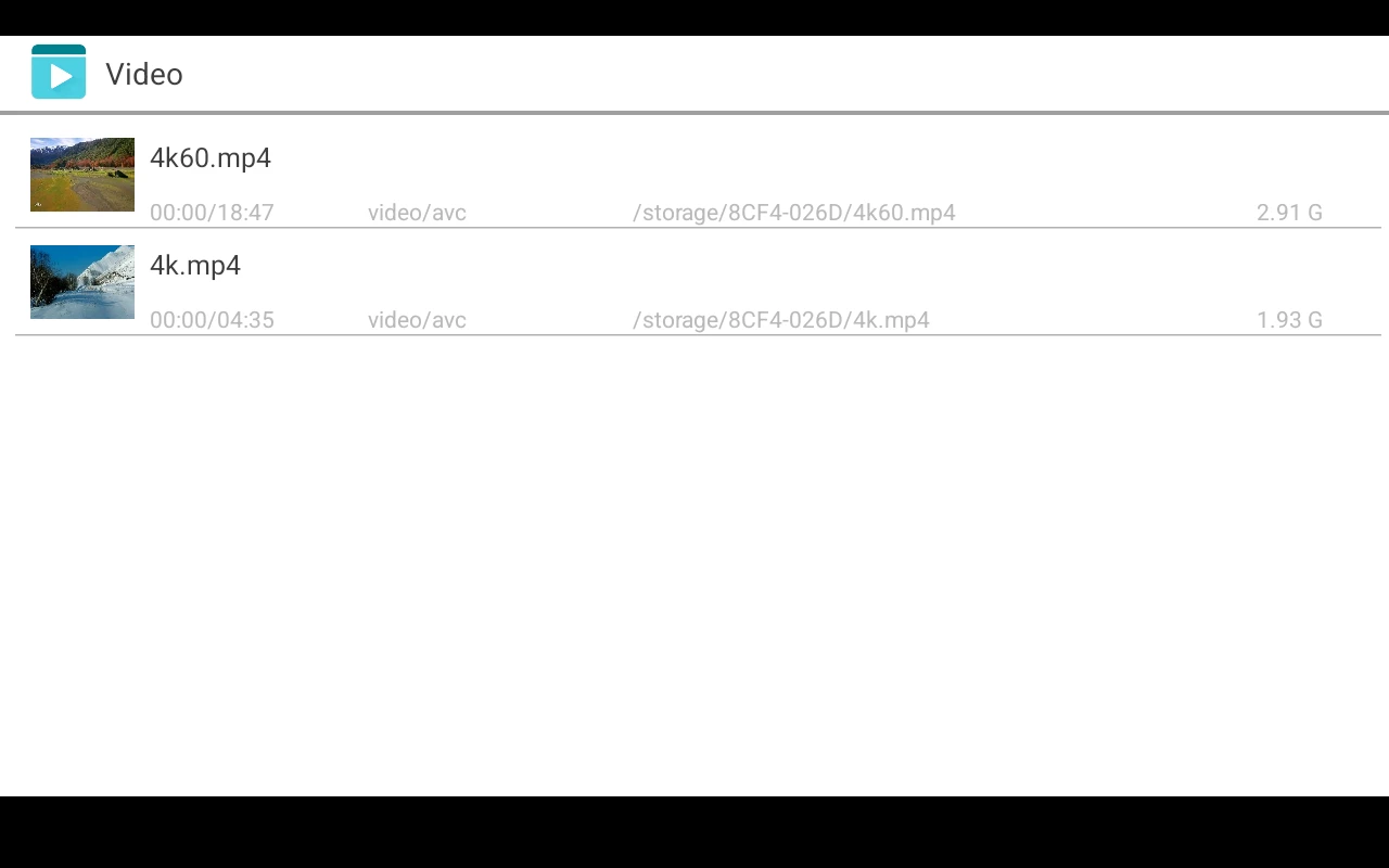
❷ Select video file to play.
Note
The EM3576 supports 4K@60 video playback and decoding of VP8, H.264, H.265, VP9, and AV1, but H.265 compatibility depends on specific encoding profiles.